Rockwell Automation Publication 1769-UM021G-EN-P - October 2015 189
Use I/O Modules with CompactLogix 5370 L2 Controllers Chapter 8
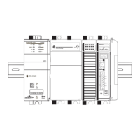
Figure 29 shows an example of ungrounded and grounded thermocouple wiring
diagrams on a 1769-L27ERM-QBFC1B controller.
Figure 29 - 1769-L27ERM-QBFC1B Controller Thermocouple Wiring Diagrams
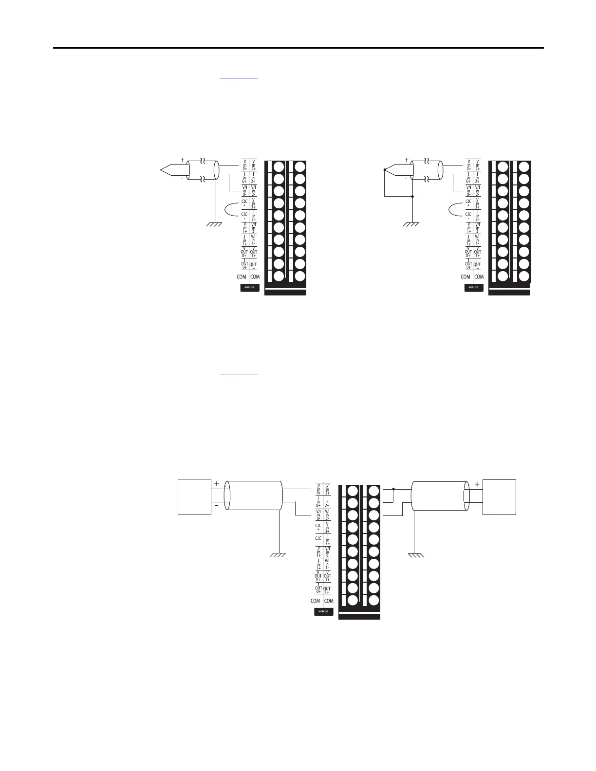
Figure 30 shows an example of devices with differential connections wired to the
embedded analog inputs on a 1769-L27ERM-QBFC1B controller when it is
operating with voltage or current input types.
Figure 30 - 1769-L27ERM-QBFC1B Controller Differential Connections Diagrams
Earth Ground
Ungrounded Thermocouple Grounded Thermocouple
Earth Ground
IMPORTANT: You must order Cold Junction Connectors, catalog number
1769-CJC, separately from the CompactLogix 5370 L2 controllers.
Differential
Voltage
Trans mitter
Earth Ground
Ground the shield
locally at the
module.
Differential
Current
Trans mitter
Voltage Input Type
Differential Voltage
Connections
Current Input Type
Differential Current
Connections
IMPORTANT: For both
input types, we
recommend that you
use Belden #8761or
equivalent cable.
Earth Ground
Ground the shield
locally at the
module.
 Loading...

