Rockwell Automation Publication 1794-IN102D-EN-P - July 2018 13
FLEX I/O AC Digital Input Modules
2. For 1794-TB2, 1794-TB3, or 1794-TB3S – Connect the associated
120V AC common (L2) of the isolated supply to the corresponding
odd-numbered terminals on the 0...15 row A for each input as indicated
in the Wiring Connections for 1794-IA8I table.
For 1794-TBN – Connect the associated 120V AC common lead (L2)
of the isolated supply to the corresponding odd-numbered terminal
1...15 on the 34...51 row (C) as indicated in the Wiring Connections for
1794-IA8I table.
IMPORTANT Individual isolated 120V AC L1 power leads must be run externally to
each of the input devices.
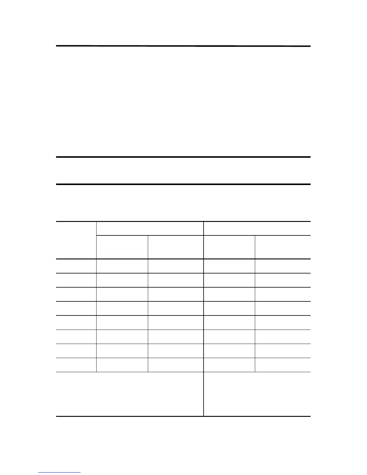
Wiring Connections for 1794-IA8I
1794-TB2, 1794-TB3, 1794-TB3S 1794-TBN
Input Input Terminal
120V AC L2
Common
Input Terminal
120V AC L2
Common
Input 0 A-0 A-1 B-0 C-1
Input 1 A-2 A-3 B-2 C-3
Input 2 A-4 A-5 B-4 C-5
Input 3 A-6 A-7 B-6 C-7
Input 4 A-8 A-9 B-8 C-9
Input 5 A-10 A-11 B-10 C-11
Input 6 A-12 A-13 B-12 C-13
Input 7 A-14 A-15 B-14 C-15
A = Even-numbered terminals 0...14 for customer
connections; corresponding odd-numbered 120V AC
common L2 terminals 1...15 for customer connections from
isolated power supply.
B = Even-numbered terminals 0...14 for
customer connections;
C = Odd-numbered 120V AC common L2
terminals 1...15 for customer connections
from isolated power supply.

 Loading...


