Publication 1794-6.5.8 - January 2010
Module Programming 35
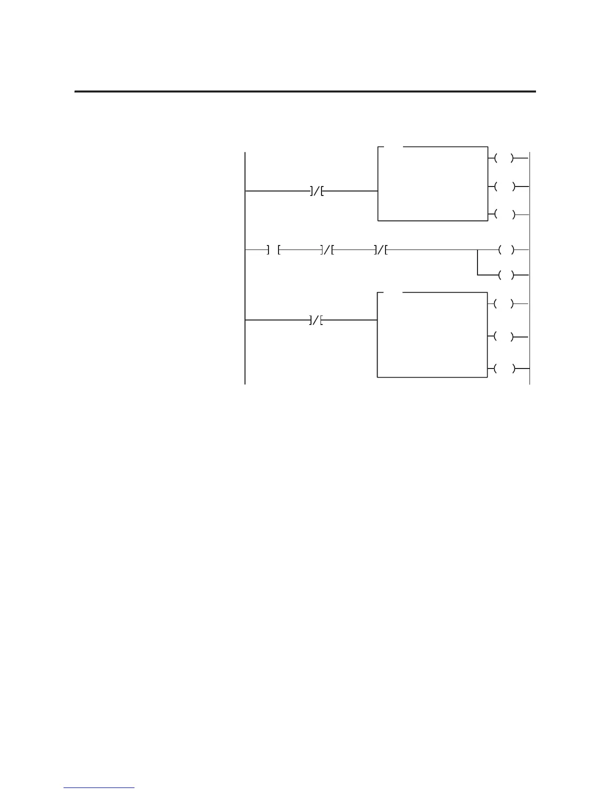
Figure 1.3
PLC-3 Family Sample Program Structure for a 1794-IF2XOF2I Module
PLC-5 Programming
The PLC-5 program is very similar to the PLC-3 program with the
following exceptions:
• block transfer enable bits are used instead of done bits as the
conditions on each rung.
• separate block transfer control files are used for the block
transfer instructions.
EN
BTR
BLOCK XFER READ
RACK:
GROUP:
MODULE:
CONTROL:
02
02
0
#B9:0
DATA FILE:
LENGTH:
#B10:0
7
EN
BTW
BLOCK XFER WRITE
RACK:
GROUP:
MODULE:
CONTROL:
02
02
0
#B9:0
DN
DATA FILE:
LENGTH:
#B11:0
7
B9:0
05
Block Transfer
Read Done Bit
ER
Enable
Done
Error
12
15
13
Enable
Done
Error
02
05
03
Block Transfer
W
rite Done Bit
1
3
DN
ER
B9:0
15
Program
Action
At power-up in RUN mode, or when the
processor is switched from PROG to RUN,
the user program enables a block transfer
read.
Thereafter, the program continuously
performs read block transfers and write
block transfers.
Note: You must create the data file
for the block transfers before you
enter the block transfer instructions.
2
14
B10:5
15
13
Power-up Bit
FP Bit
CF Bit
B11:6
15
IC Bit
B10:5 B10:5
Then it initiates a block transfer write to
configure the module and send data values
This rung toggles the Initate Configuration
bit from 0 to 1 to 0
L
14
B11:6
 Loading...


