Publication 1794-6.5.8 - January 2010
Input, Output, Status and Configuration Files for Analog Modules when used with ControlNet 103
Input Data Behavior Upon
Module Removal
I/O module input data sent by the adapter upon module removal is
configurable. The adapter can:
• reset the module output data to zero (reset)
• leave the module output data in the last state before module
removal (hold last state)
4 Input Isolated Analog Module (Cat. No. 1794-IF4I, 1794-IF4IXT,
1794-IF4ICFXT) Table Mapping
Set EN bit Off (0) for Configuration block. Module actions (Reset, Safe
State and Hold Last State) are set using programming software.
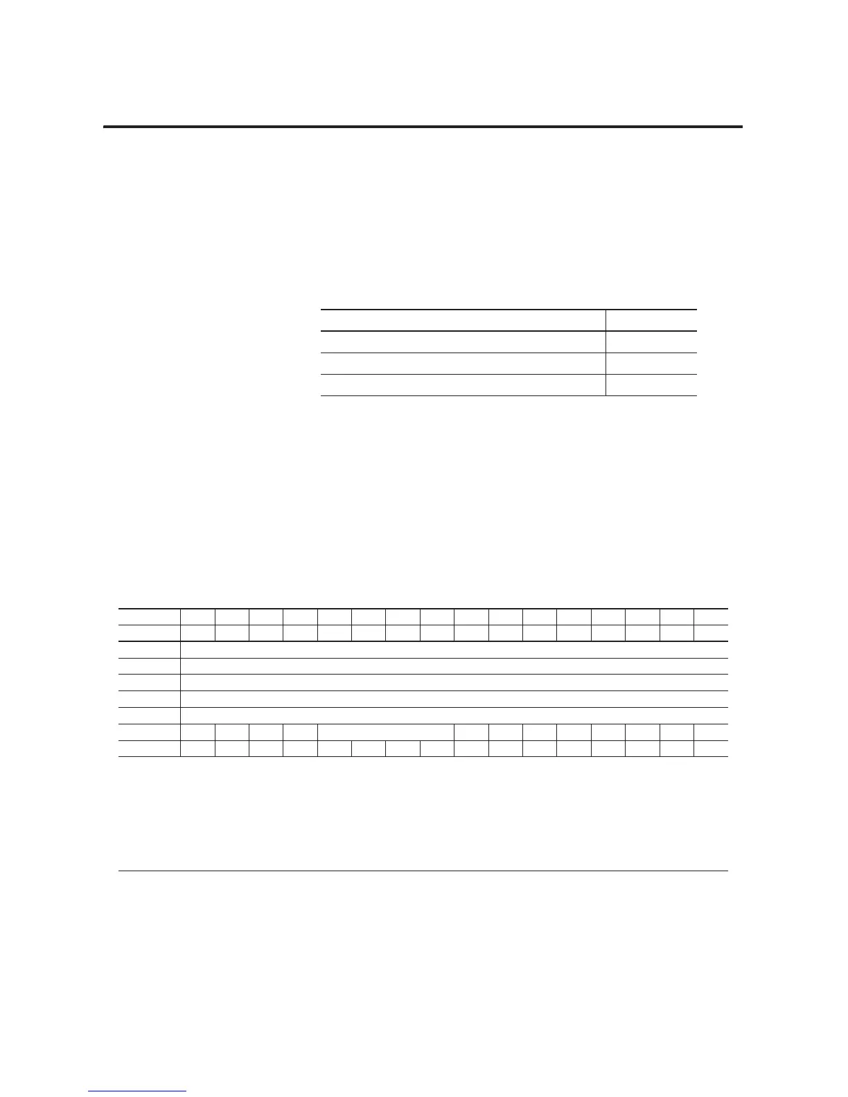
To find the image table for: See page:
4 Input Isolated Analog Module (Cat. No. 1794-IF4I) 103
4 Output Isolated Analog Module (1794-OF4I) 108
Isolated Analog Combo Module (1794-IF2XOF2I) 113
Table 6.1 Input Map
Dec. 15 14 13 12 11 10 9876543210
Oct. 17 16 15 14 13 12 11 10 76543210
Word 0 Analog Value Channel 0
Word 1 Analog Value Channel 1
Word 2 Analog Value Channel 2
Word 3 Analog Value Channel 3
Word 4 Real Time Sample
Word 5 PU FP CF 0 Reserved 00000BDDN0
Word 600000000V3V2V1V0U3U2U1U0
Where :
PU = Power up inconfigured
FP = Field power off
CF = In configuration mode
BD = Bad calibration
DN = Calibration accepted
U = Underrange for specified channel
V = Overrange for specified channel
 Loading...


