Publication 1794-6.5.8 - January 2010
Communication and I/O Image Table Mapping with the DeviceNet/ControlNet Adapter 79
Mapping Data into the
Image Table
FLEX I/O analog modules are supported by the DeviceNet adapter.
4 Input Isolated Analog Module (Cat. No. 1794-IF4I) Image Table
Mapping
Module Description Catalog
Number:
For image table mapping refer to:
4 Input Isolated Analog Module 1794-IF4I page 5-79
4 Output Isolated Analog Module 1794-OF4I page 5-86
2 in/2 out Isolated Analog Combo Module 1794-IF2XOF2I page 5-91
Module
Image
I/O Image
Input Data Channel 0
Input Data Channel 1
Input Data Channel 2
Input Data Channel 3
Input Size
Output Size
0 to 8 Word
1 to 7Words
Real Time Sample
PU FP CF BD DN
UnderrangeOverrange
Channel Filters
Channel Configuration
Real Time Sample Programmed Interval
IC
RV QK CK GO
Channel #
Set to 0EN
1
Not used
Not used
Not used
TR IT
Table 5.1
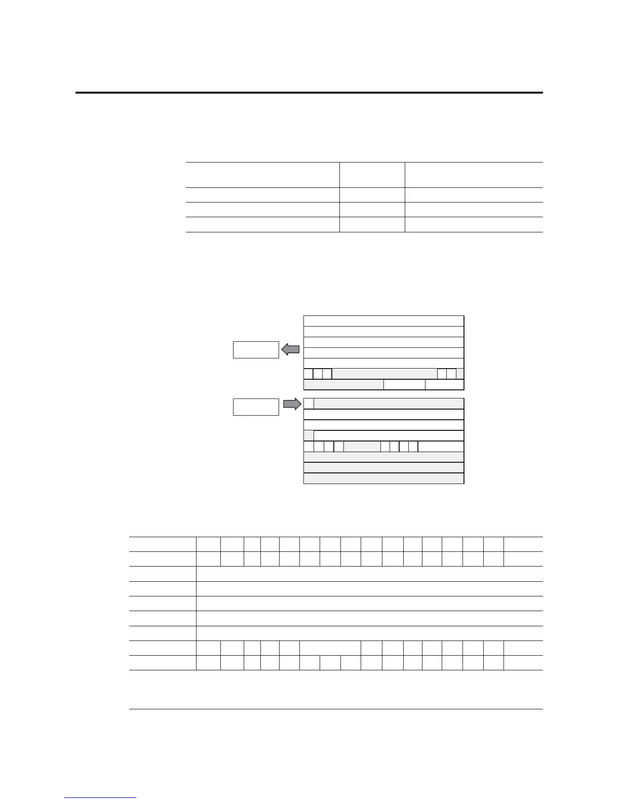
Analog Input Module (1794-IF4I, 1794-IF4ICFXT) Read
Word/Dec. Bit 15 14 13 12 11 10 09 08 07 06 05 04 03 02 01 00
Word/Octal Bit 17 16 15 14 13 12 11 10 07 06 05 04 03 02 01 00
Read Word 1 Analog Value Channel 0
Word 2 Analog Value Channel 1
Word 3 Analog Value Channel 2
Word 4 Analog Value Channel 3
Word 5 Real Time Sample
Word 6 PU FP CF 0 Reserved 0 0 0 0 0 BD DN 0
Word 7 0 0 0 0 0 0 0 0 V3 V2 V1 V0 U3 U2 U1 U0
Where:
PU = Power up unconfigured state
FP = Field power off
CF = In configuration mode
BD = Calibration bad
DN = Calibration accepted
U = Under range for specified channel
V = Overrange for specified channel
 Loading...


