20 Rockwell Automation Publication 857-QS001B-EN-P - April 2017
Chapter 2 Mounting and Wiring Instructions
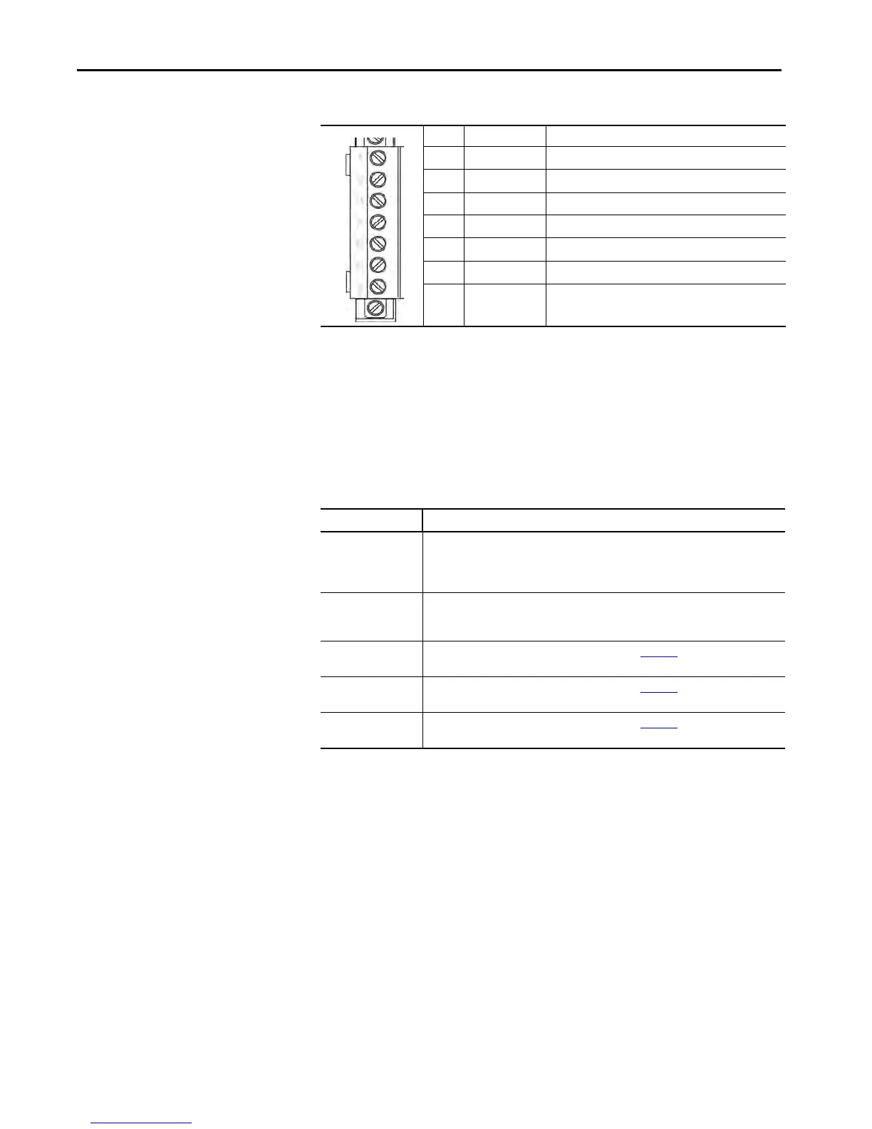
Table 10 - Terminal X6 with DI19/DI20 Option
Voltage Measurement Mode
The 857 Protection System can be connected to line-to-line or phase-to-
ground voltages. The connection is dependent on the application and available
voltage transformers. Set the configuration parameter “Voltage measurement
mode” according to the used connection.
Table 11 - Available Voltage Modes
The overvoltage protection is based on the line-to-line voltage regardless of the
measurement mode.
The wiring of the secondary circuits of voltage transformers to the device
terminal depends on the selected voltage-measuring mode.
No: Symbol Description
1 DI19 Digital input 19
2 DI19 Digital input 19
3 DI20 Digital input 20
4 DI20 Digital input 20
5— —
6 S1>+ Arc sensor 1, positive connector
(1)
(1) Arc sensor itself is polarity free.
7 S1>– Arc sensor 1, negative connector
(1)
Mode Description
“2LL+U
0
” The device is connected to line-to-line voltages U
12
(X1-11 and X1-12) and U
23
(X1-13 and
X1-14). Also to zero sequence voltage U
0
(X1-17 and X1-18). The phase-to-ground
voltages are calculated. The network must use only three wires. Any neutral wire must not
exist (two PTs/VTs in open Delta).
“3LN” The device is connected to phase-to-ground voltages U
L1
(X1-11 and X1-12), U
L2
(X1-13
and X1-14), and U
L3
(X1-17 and X1-18). The zero sequence voltage is calculated. A neutral
wire can exist (three PTs/VTs “Y” connected).
“1LL+U
0
/LLy” This mode is used with the Synchrocheck function. See Chapter 3, Synchrocheck Protection
(25) of the user guide for more information.
2LL/LLy” This mode is used with the Synchrocheck function. See Chapter 3, Synchrocheck Protection
(25) of the user guide for more information.
“LL/LLy/LLz” This mode is used with the Synchrocheck function. See Chapter 3
, Synchrocheck Protection
(25) of the user guide for more information.
 Loading...