Rockwell Automation Publication 857-QS001B-EN-P - April 2017 33
Installation Chapter 4
Step 6: Configuring the
Protection System Using
SetPointPS
Once the connection between the SetPointPS software and the Protection
System is established, you can read and modify the data within the device.
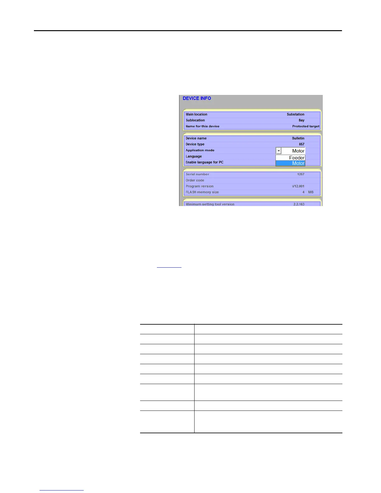
1. Define the mode of protection that the relay performs; Motor
Protection or Feeder Protection. Make the mode selection in the
Application Mode parameter setting of the Device Info screen.
2. Enter the variables associate with the connected load and the control
unit that is used to start and stop the load.
3. The fundamental settings that are related to the load and controller
characteristics must be entered in the SCALING section of the
SetPointPS software.
Figure 10
shows the two variations of the scaling input screens from the
SetPointPS software; Motor protective mode and Feeder protective
mode. Notice the differences in the first portion of the configure
screens. For motor protection, the full load current of the motor must be
added. In the Feeder Mode, only the main current transformer details
are required. The following data must be entered to provide accurate
protection.
If VT/PT inputs are connected to the Protection System for metering, a
selection must be made in the Voltage Measurement Mode selection-area.
Motor nom current Motor full load current (for motor protective mode only).
CT primary Rated phase CT primary current ratio, for example, 500 A.
CT secondary Rated phase CT secondary current, for example, 5 A.
VT/PT primary If applied, rated VT/PT primary voltage ratio, for example, 4160V.
VT/PT secondary If applied, rated VT/PT secondary voltage, for example, 120V.
I
01
CT primary Rated value of I
0
1 Ground Fault CT primary current.
I
01
CT secondary Rated value of I
0
1 Ground Fault CT secondary current.
Rated I
0
1 input of the relay. 5 A or 1 A, as specified in the order code of the device.
I
02
CT Ground Fault Rated value of I
0
2 CT Ground Fault primary current.
I
02
CT secondary current Rated value of I
0
2 CT secondary current.
Rated I
0
2 input of the relay. 5 A, 1 A, or 0.2 A, as specified in the order code of the
device.
 Loading...