34 Rockwell Automation Publication 857-QS001B-EN-P - April 2017
Chapter 4 Installation
Typical entries within the Voltage Measurement Mode are: Two open delta
VT/PTs setting to be 2LL+U
0
, 3 VT/PTs in wye setting to be 3LN.
The CT input of the relay, 5 A or 1 A, are specified in the order code of the
device. The rated input values are equal to or less than the rated secondary
value of the CT.
The rated CT secondary can be greater than the rated input, but the
continuous current must be less than four times the rated input. The rated CT
secondary can also be less than the rated input, but the measurement accuracy
near zero current decreases.
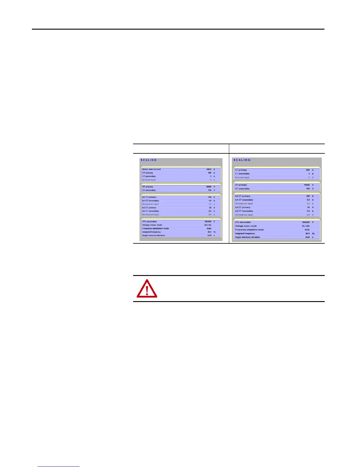
Figure 10 - Scaling Input Screens
4. The factory default protective-element settings within the relay only
provide minimal levels of protection.
Motor Protective Mode Feeder Protective Mode
ATTENTION: You must select and configure the appropriate protective
elements in relationship to the application mode selected.
 Loading...