Rockwell Automation Publication 857-QS001B-EN-P - April 2017 15
Mounting and Wiring Instructions Chapter 2
Measuring and Control
Connections
Allen-Bradley 857 Protection Relay is connected to the protected object
through these measuring and control connections.
The following terminal connections are shown in this quick start:
• Te r m i n a l X 1 L e f t S i d e
on page 16
• Te r m i n a l X 1 R i g h t S i d e on page 16
• Te r m i n a l X 2 on page 16
• Te r m i n a l X 3 on page 17
• Te r m i n a l X 7 on page 17
• Terminal X8 Model 857-3C7 on page 18
• Terminal X8 Model 857-3C8 on page 19
• Te r m i n a l X 6 on page 19
• Terminal X6 with DI19/DI20 Option
on page 20
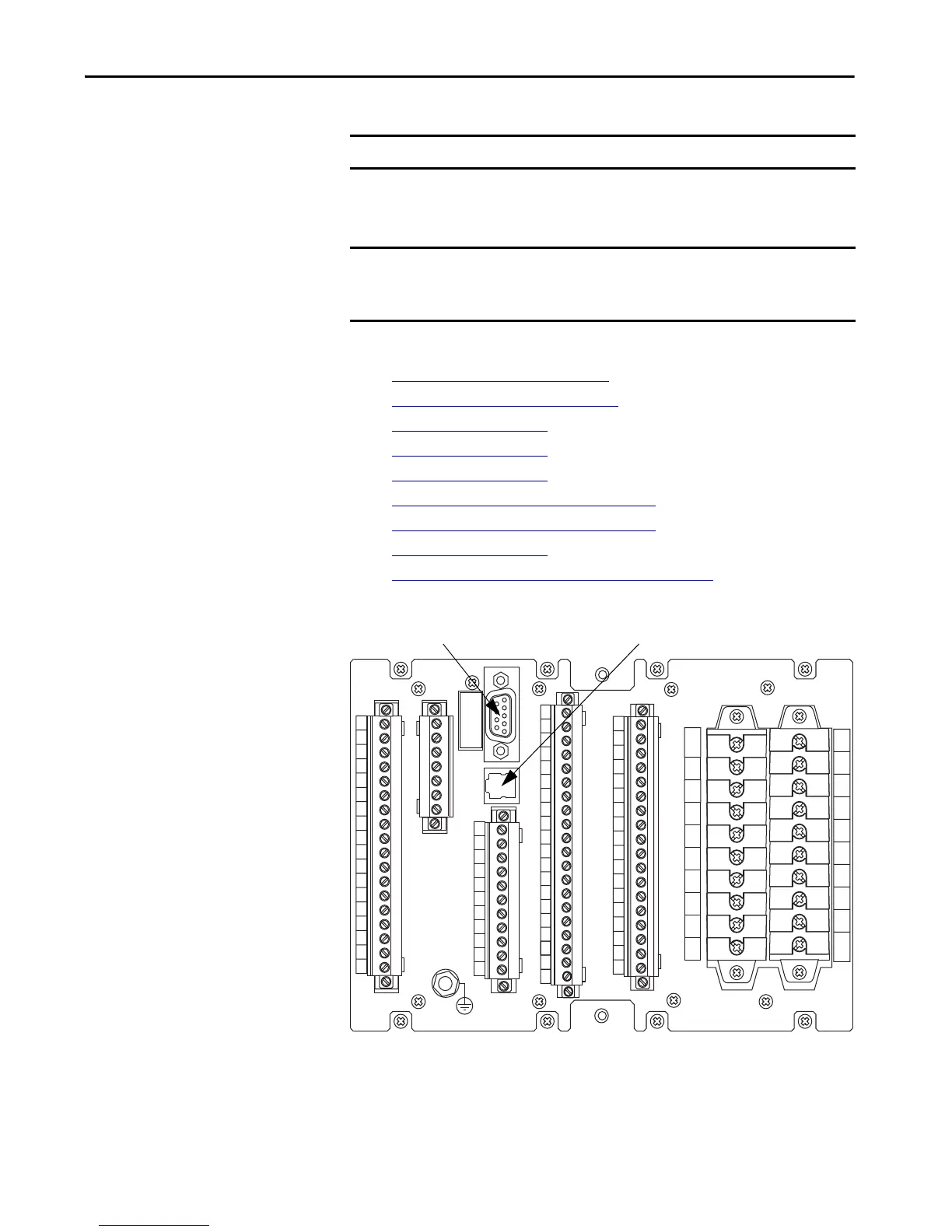
Figure 3 - Example of Allen-Bradley 857 Back Panel Communication Connection
IMPORTANT Some cards configurations are optional
IMPORTANT Settings that are associated with options or accessories, such as RTD
scanners require the option or accessory to be installed or connected before
being made available for configuration
1
2
3
4
5
6
7
8
9
10
11
12
13
14
15
16
17
18
X3
X1
REMOTE
(TTL)
1
3
5
7
9
11
13
15
17
19
2
4
6
8
10
12
14
16
18
20
X6
X2
1
2
3
4
5
6
7
8
9
10
11
12
13
14
15
16
17
18
X7
1
2
3
4
5
6
7
8
9
10
11
1
2
3
4
5
6
7
8
9
10
11
12
13
14
15
16
17
18
19
20
X8
Communication Option 1
Communication Option 2
 Loading...