16 Rockwell Automation Publication 857-QS001B-EN-P - April 2017
Chapter 2 Mounting and Wiring Instructions
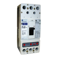
Table 2 - Terminal X1 Left Side
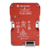
Table 3 - Terminal X1 Right Side
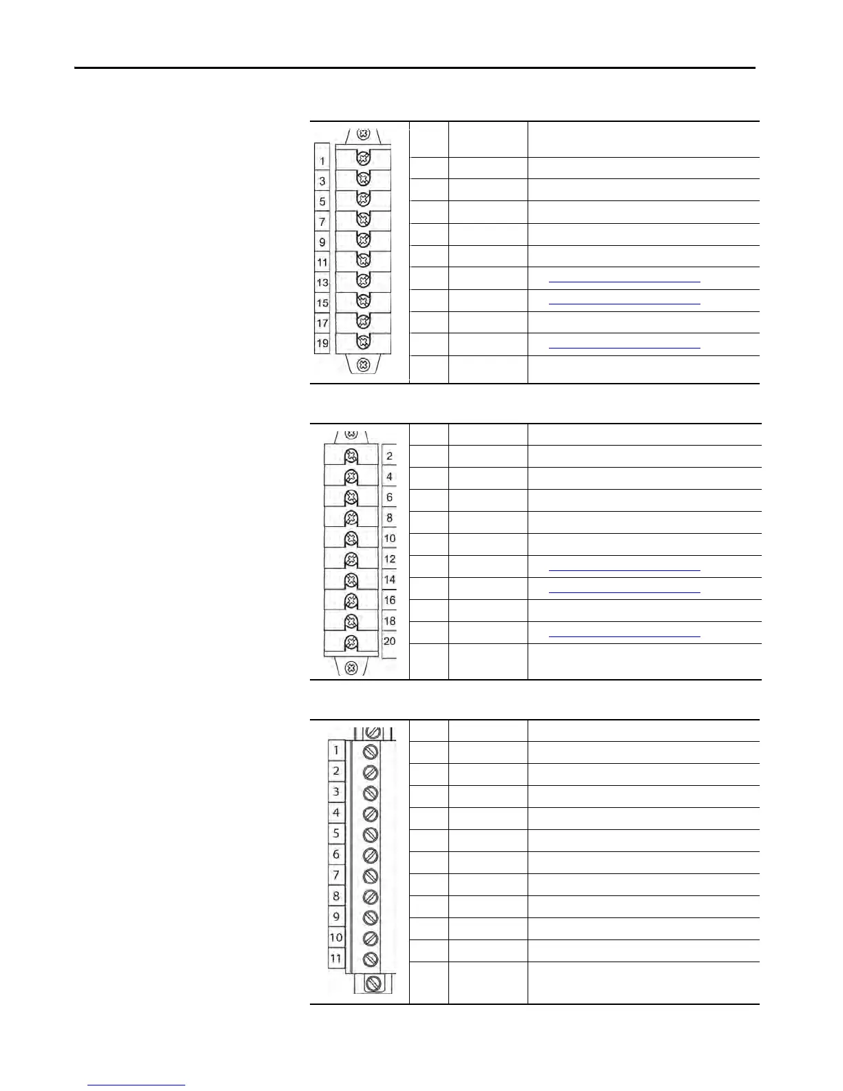
Table 4 - Terminal X2
No: Symbol Description
1 IL1(S1) Phase current L1 (S1)
3 IL2(S1) Phase current L2 (S1)
5 IL3(S1) Phase current L3 (S1)
7 Io1/1A(S1) Residual current I/O1(S1)
9 Io2/5A(S1) Residual current I/O2(S1)
11 Ua See Voltage Measurement Mode
on page 20
13 Ub See Voltage Measurement Mode on page 20
15 -- --
17 Uc See Voltage Measurement Mode on page 20
19 -- --
No: Symbol Description
2 IL1(S2) Phase current L1 (S2)
4 IL2(S2) Phase current L2 (S2)
6 IL3(S2) Phase current L3 (S2)
8 Io1/1A(S2) Residual current I/O1 (S2)
10 Io2/5A(S2) Residual current I/O2 (S2)
12 Ua See Voltage Measurement Mode
on page 20
14 Ub See Voltage Measurement Mode on page 20
16 -- --
18 Uc See Voltage Measurement Mode on page 20
20 -- --
No: Symbol Description
1 A5 Alarm relay 5
2 A5 Alarm relay 5
3 A4 Alarm relay 4
4 A4 Alarm relay 4
5 A3 Alarm relay 3
6 A3 Alarm relay 3
7 A2 Alarm relay 2
8 A2 Alarm relay 2
9 IF COM Internal fault relay, common connector
10 IF NC Internal fault relay, normal closed connector
11 IF NO Internal fault relay, normal open connector
 Loading...