FLEX™ I/O Isolated Input/Output Analog Module 3
Publication 1794-IN039F-EN-P - November 2011
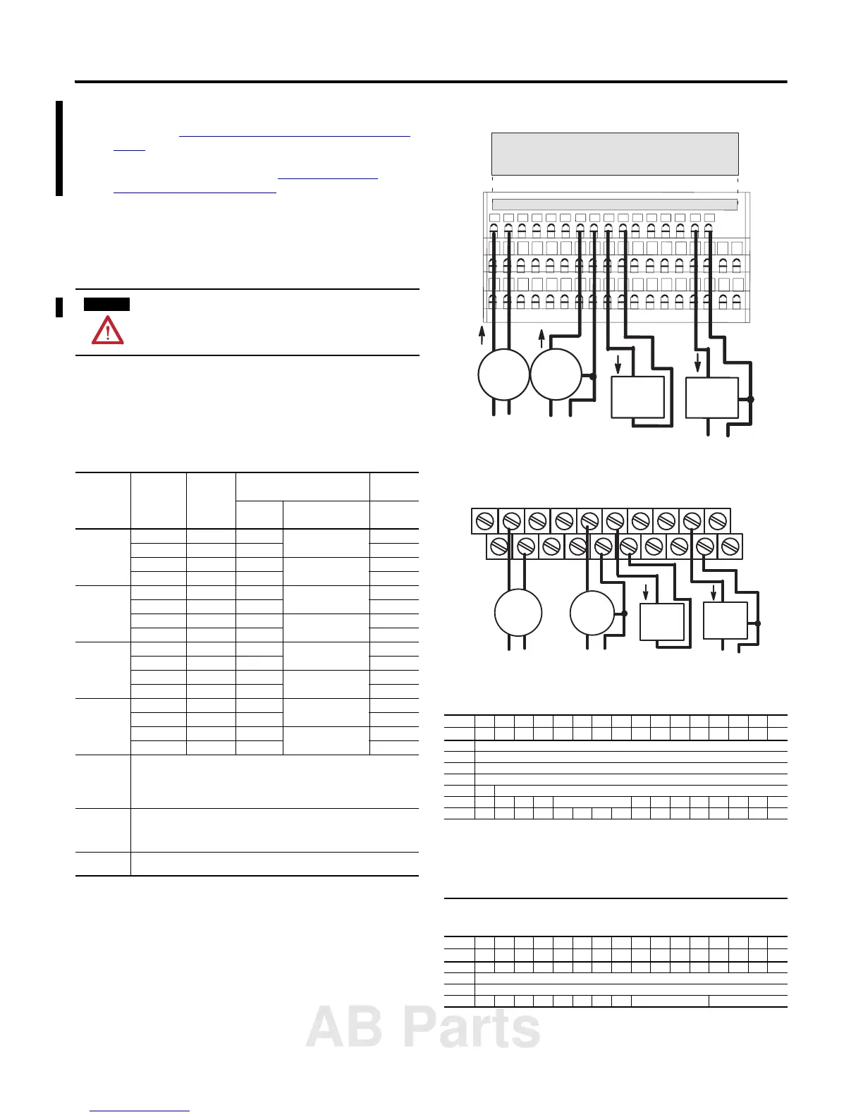
2. 1794-TB2, 1794-TB3, 1794-TB3S, 1794-TB3T, 1794-TB3TS: Connect
each channel signal return to numbered terminals on the 0…15 row (A) as
indicated in the Wiring Connections for 1794-IF2XOF2I Input/Output
Module table. Use Belden 8761 cable for signal wiring.
1794-TBN: Connect each channel signal return to odd-numbered
terminals on row (C) as indicated in the
Wiring Connections for
1794-IF2XOF2I Input/Output Module table.
3. Connect any signal wiring shields to functional ground as near as possible
to the module.
1794-TB3T or 1794-TB3TS only: Connect to earth ground terminals
C-39…C-46.
4. Connect the +V DC power to terminal 34 on the 34…51 row (C) and -V
common/return to terminal 16 on the B row.
5. If daisychaining power to the next terminal base, connect a jumper from
terminal 51 (+V DC) on this base unit to terminal 34 on the next base unit.
6. If continuing DC common (-V) to the next base unit, connect a jumper
from terminal 33 (common) on this base unit to terminal 16 on the next
base unit.
1794-TB2, 1794-TB3, 1794-TB3S, 1794-TB3T and 1794-TB3TS Terminal Base
Wiring
1794-TBN Terminal Base Wiring
To reduce susceptibility to noise, power analog modules and digital
modules from separate power supplies.
Wiring Connections for 1794-IF2XOF2I Input/Output Module
Channel Signal Type Label
Markings
1794-TB2, 1794-TB3, 1794-TB3S,
1794-TB3T, 1794-TB3TS
1794-TBN
Terminal Shield (1794-TB3T,
1794-TB3TS)
Terminal
Input 0 Current I0 A-0 C-39 B-0
Current I0 ret A-1 C-1
Voltage V0 A-2 C-40 B-2
Voltage V0 ret A-3 C-3
Input 1 Current I1 A-4 C-41 B-4
Current I1 ret A-5 C-5
Voltage V1 A-6 C-42 B-6
Voltage V1 ret A-7 C-7
Output 0 Current I2 A-8 C-43 B-8
Current I2 ret A-9 C-9
Voltage V2 A-10 C-44 B-10
Voltage V2 ret A-11 C-11
Output 1 Current I3 A-12 C-45 B-12
Current I3 ret A-13 C-13
Voltage V3 A-14 C-46 B-14
Voltage V3 ret A-15 C-15
-V DC common 1794-TB2, 1794-TB3, 1794-TB3S: Terminals B-16…B-33 are internally connected in the
terminal base unit.
1794-TBN: Terminals B-16 and B-33 are internally connected in the terminal base unit.
1794-TB3T, 1794-TB3TS: Terminals 16, 17, 19, 21, 23, 25, 27, 29, 31 and 33 are internally
connected in the terminal base unit.
+V DC power 1794-TB3, 1794-TB3S: Terminals 34…51 are internally connected in the terminal base unit.
1794-TB3T, 1794-TB3TS: Terminals 34, 35, 50 and 51 are internally connected in the terminal
base unit.
1794-TBN, 1794-TB2: Terminals 34 and 51 are internally connected in the terminal base unit.
Chassis ground
(shield)
1794-TB3T, 1794-TB3TS: Terminals 39…46 are internally connected to chassis ground.
Input Map
Dec 15 14 13 12 11 10 9 8 7 6 5 4 3 2 1 0
Oct 17 16 15 14 13 12 11 10 7 6 5 4 3 2 1 0
Word 0 Analog value for input channel 0
Word 1 Analog value for input channel 1
Word 2 Read back output channel 0
Word 3 Read back output channel 1
Word 4 0 Real-time sample
Word 5 PU FP CF 0 Reserved 0 0 0 0 0 BD DN 0
Word 6 0 0 0 0 P1 P0 0 0 0 0 V1 V0 W1 W0 U1 U0
Where: PU = Power up inconfigured
FP = Field power off
CF = In configuration mode
BD = Calibration bad
DN = Calibration done
U = Under range for specified channel
W = Wire off current loop status for output channels 0 and 1
V = Over range for specified channel
P = Outputs holding in response to Q0 and Q1
Output Map
Dec 15 14 13 12 11 10 9 8 7 6 5 4 3 2 1 0
Oct 17 16 15 14 13 12 11 10 7 6 5 4 3 2 1 0
Word 0 EN S1 S0 0 0 0 0 0 0 0 0 0 0 0 0 0
Word 1 Analog output data – channel 0
Word 2 Analog output data – channel 1
Word 3 0 0 0 0 0 0 0 0 Input channel 1 filter Input channel 0 filter
I
I
I
I
+
+
+
+
+
+
+
-
-
-
-
-
0 1 2 3 4 5 6 7 8 9 10 11 12 13 14 15
16 17 18 19 20 21 22 23 24 25 26 27 28 29 30 31 32 33
34 35 36 37 38 39 40 41 42 43 44 45 46 47 48 49 50 51
45753
Row A
Row B
Row C
Current
input
Voltage
input
Current
output
device
Voltage
output
device
AC or DC
4-wire current
transmitter
DC only
3-wire
transmitter
Current only
2-wire output
device
DC only
3-wire output
device
Label placed at top of wiring area
Row A
Row B
Row C
1794-TB3S
+
+
+
I
+
+
I
+
+
-
-
-
-
-
16
34
1
3
5
7
9
11
13
15 51
024
6
8
10
12 14
33
45754
Even-numbered terminals 0...1416 33
34 51
Row B
Row C
DC only
3-wire output
device
Current only
2-wire output
device
DC onlyAC or DC
4-wire current
transmitter
Current
input
Voltage
input
Current
output
device
Voltage
output
device
3-wire
transmitter
AB Parts
 Loading...


