PanelView Component HMI Terminals 13
Publication 2711C-IN001H-EN-P - July 2014
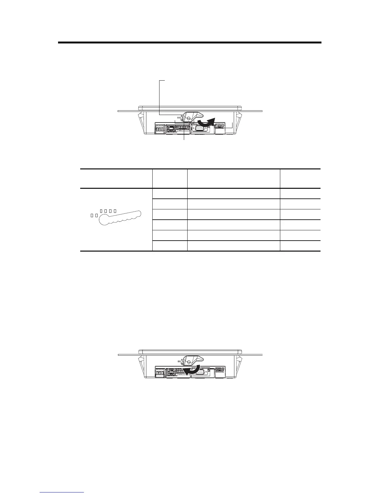
4. Rotate each lever in the direction indicated until it is in the final latch position.
Use this table as a guide to provide an adequate gasket seal between the terminal and the panel.
Remove the C200, C300, or C600 Terminal from the Panel
Follow these steps to remove the terminal from the panel.
1. Disconnect power to the terminal.
2. For a C600 (2711C-T6M, -T6C Series C or later, 2711C-T6T Series A or later only) terminal,
release the mounting lever by rotating it in the direction indicated, slide it to the bottom of the
mounting slot, and remove it.
Terminal Markings for
Alignment
Lever
Position
Panel Thickness Range
Typical
Gauge
1 1.52…2.01 mm (0.060…0.079 in.) 16
2 2.03…2.64 mm (0.08…0.104 in.) 14
3 2.67…3.15 mm (0.105…0.124 in.) 12
4 3.17…3.66 mm (0.125…0.144 in.) 10
5 3.68…4.16 mm (0.145…0.164 in.) 8/9
6 4.19…4.75 mm (0.165…0.187 in.) 7
6
Rotate until the short, flat side of the lever
aligns with an alignment mark on the terminal.
Six alignment marks
44907
61
 Loading...