Rockwell Automation Publication 2711P-TD001D-EN-P - February 2011
Wiring and Grounding Guidelines for PanelView Plus Terminals 9
Earth/Ground Connection for Nonisolated DC Terminals
PanelView Plus devices with a nonisolated DC power supply have a functional
earth/ground (FE) terminal that you must connect to a low-impedance
earth/ground:
• The 700 to 1500 terminals have the functional earth/ground connection
on the rear of the display module.
• The 400 and 600 terminals have the functional earth/ground connection
on the power input terminal block.
The functional earth terminal wiring requires a minimum wire gauge.
On most PanelView Plus DC terminals, the earth/ground terminal is internally
connected to the DC- terminal within the product.
The functional earth terminal is typically connected to a system grounding bus. If
the grounding bus has tapped holes, the conductor from the functional earth
terminal must have a ground lug on the ground bus end. A bolt should pass
through a star washer, then through the ground conductor lug, then into the
ground bus.
Use the shortest, practical wire length to connect the functional earth/ground to
a low-impedance earth/ground. The ground wire must be either green or green
with a yellow stripe.
Refer to local wiring codes and regulations for grounding requirements.
IMPORTANT
The functional earth connection to ground is mandatory. This
connection is required for noise immunity, reliability, and
Electromagnetic Compliance (EMC) with the European Union (EU)
EMC directive for CE-mark conformance.
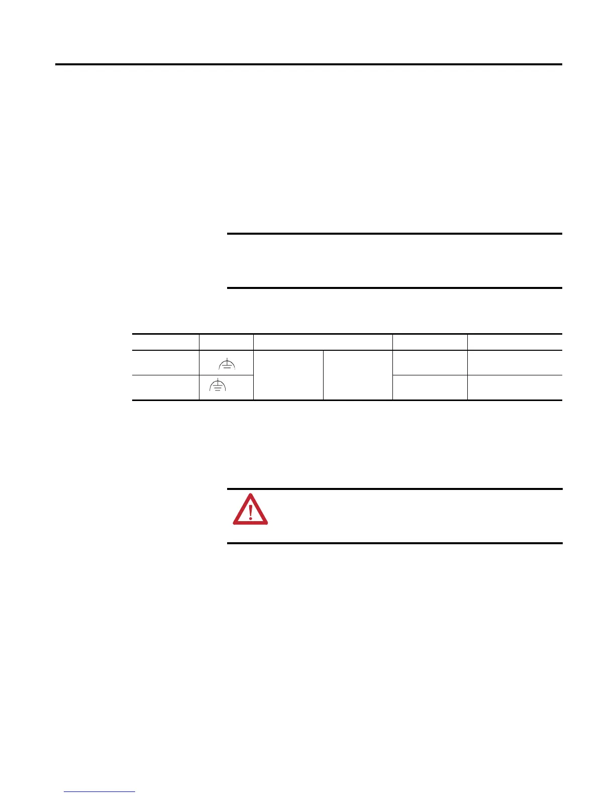
Table 4 - Functional Earth Wiring
Terminal Model FE Symbol Wire Type Wire Gauge Terminal Screw Torque
400 and 600
(1)
Cu 90 °C (194 °F)
Copper
Stranded or solid
2.1…3.3 mm
2
(14…12 AWG)
0.45…0.56 N•m
(4…5 lb•in)
700 to 1500
(2)
GND
2.1…5.3 mm
2
(14…10 AWG)
1.13…1.36 N•m
(10…12 lb•in)
(1) Includes the PanelView Plus Compact 400 and 600 terminals.
(2) Includes the PanelView Plus Compact 1000 terminal.
ATTENTION: Damage or malfunction can occur when a voltage potential
exists between two separate ground points. Make sure the PanelView
Plus terminal does not serve as a conductive path between ground points
at different potentials.
 Loading...