English-10
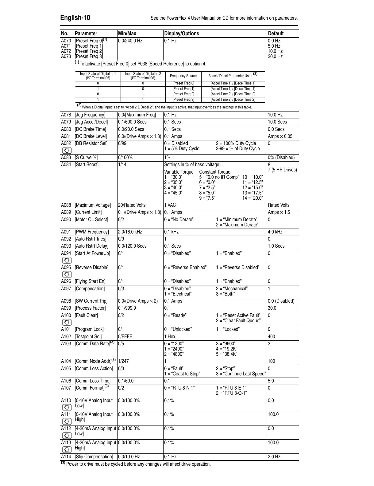
A070
A071
A072
A073
[Preset Freq 0]
(1)
[Preset Freq 1]
[Preset Freq 2]
[Preset Freq 3]
0.0/240.0 Hz 0.1 Hz 0.0 Hz
5.0 Hz
10.0 Hz
20.0 Hz
(1)
To activate [Preset Freq 0] set P038 [Speed Reference] to option 4.
A078 [Jog Frequency] 0.0/[Maximum Freq] 0.1 Hz 10.0 Hz
A079 [Jog Accel/Decel] 0.1/600.0 Secs 0.1 Secs 10.0 Secs
A080 [DC Brake Time] 0.0/90.0 Secs 0.1 Secs 0.0 Secs
A081 [DC Brake Level] 0.0/(Drive Amps × 1.8) 0.1 Amps Amps × 0.05
A082 [DB Resistor Sel] 0/99 0 = Disabled
1 = 5% Duty Cycle
2 = 100% Duty Cycle
3-99 = % of Duty Cycle
0
A083 [S Curve %] 0/100% 1% 0% (Disabled)
A084 [Start Boost] 1/14 Settings in % of base voltage. 8
7 (5 HP Drives)
V
ariable Torque Constant Torque
1 = “30.0” 5 = “0.0 no IR Comp” 10 = “10.0”
2 = “35.0” 6 = “0.0” 11 = “12.5”
3 = “40.0” 7 = “2.5” 12 = “15.0”
4 = “45.0” 8 = “5.0” 13 = “17.5”
9 = “7.5” 14 = “20.0”
A088 [Maximum Voltage] 20/Rated Volts 1 VAC Rated Volts
A089 [Current Limit] 0.1/(Drive Amps × 1.8) 0.1 Amps Amps × 1.5
A090 [Motor OL Select] 0/2 0 = “No Derate” 1 = “Minimum Derate”
2 = “Maximum Derate”
0
A091 [PWM Frequency] 2.0/16.0 kHz 0.1 kHz 4.0 kHz
A092 [Auto Rstrt Tries] 0/9 1 0
A093 [Auto Rstrt Delay] 0.0/120.0 Secs 0.1 Secs 1.0 Secs
A094 [Start At PowerUp] 0/1 0 = “Disabled” 1 = “Enabled” 0
A095 [Reverse Disable] 0/1 0 = “Reverse Enabled” 1 = “Reverse Disabled” 0
A096 [Flying Start En] 0/1 0 = “Disabled” 1 = “Enabled” 0
A097 [Compensation] 0/3 0 = “Disabled”
1 = “Electrical”
2 = “Mechanical”
3 = “Both”
1
A098 [SW Current Trip] 0.0/(Drive Amps × 2) 0.1 Amps 0.0 (Disabled)
A099 [Process Factor] 0.1/999.9 0.1 30.0
A100 [Fault Clear] 0/2 0 = “Ready” 1 = “Reset Active Fault”
2 = “Clear Fault Queue”
0
A101 [Program Lock] 0/1 0 = “Unlocked” 1 = “Locked” 0
A102 [Testpoint Sel] 0/FFFF 1 Hex 400
A103 [Comm Data Rate]
(3)
0/5 0 = “1200”
1 = “2400”
2 = “4800”
3 = “9600”
4 = “19.2K”
5 = “38.4K”
3
A104 [Comm Node Addr]
(3)
1/247 1 100
A105 [Comm Loss Action] 0/3 0 = “Fault”
1 = “Coast to Stop”
2 = “Stop”
3 = “Continue Last Speed”
0
A106 [Comm Loss Time] 0.1/60.0 0.1 5.0
A107 [Comm Format]
(3)
0/2 0 = “RTU 8-N-1” 1 = “RTU 8-E-1”
2 = “RTU 8-O-1”
0
A110 [0-10V Analog Input
Low]
0.0/100.0% 0.1% 0.0
A111 [0-10V Analog Input
High]
0.0/100.0% 0.1% 100.0
A112 [4-20mA Analog Input
Low]
0.0/100.0% 0.1% 0.0
A113 [4-20mA Analog Input
High]
0.0/100.0% 0.1% 100.0
A114 [Slip Compensation] 0.0/10.0 Hz 0.1 Hz 2.0 Hz
(3)
Power to drive must be cycled before any changes will affect drive operation.
No. Parameter Min/Max Display/Options Default
Input State of Digital In 1
(I/O Terminal 05)
Input State of Digital In 2
(I/O Terminal 06)
Frequency Source Accel / Decel Parameter Used
(2)
0 0 [Preset Freq 0] [Accel Time 1] / [Decel Time 1]
1 0 [Preset Freq 1] [Accel Time 1] / [Decel Time 1]
0 1 [Preset Freq 2] [Accel Time 2] / [Decel Time 2]
1 1 [Preset Freq 3] [Accel Time 2] / [Decel Time 2]
(2)
When a Digital Input is set to “Accel 2 & Decel 2”, and the input is active, that input overrides the settings in this table.
See the PowerFlex 4 User Manual on CD for more information on parameters.

 Loading...