176 Rockwell Automation Publication 520-UM001G-EN-E - September 2014
Appendix B Accessories and Dimensions
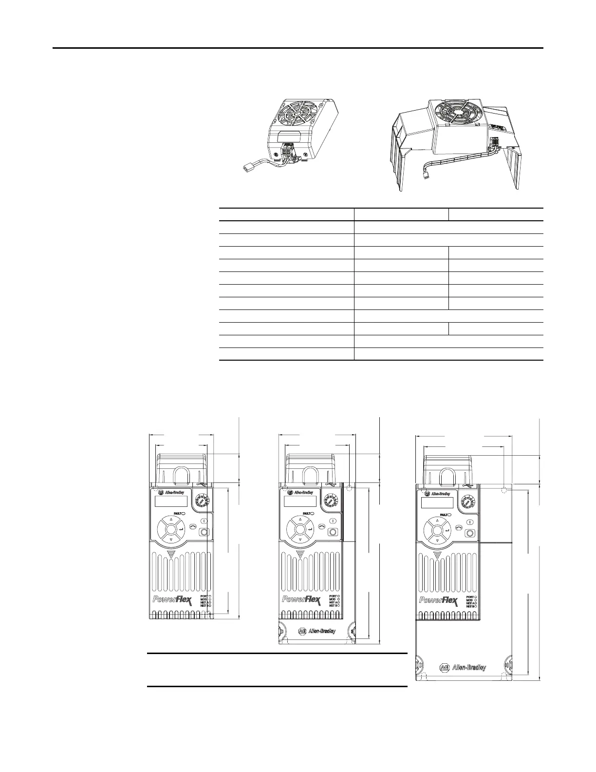
Control Module Fan Kit
IP 20/Open Type with Control Module Fan Kit – Frame A...C
Specifications 25-FAN1-70C 25-FAN2-70C
Rated Voltage 24V DC
Operation Voltage 14...27.6V DC
Input Current 0.1 A 0.15 A
Speed (Reference) 7000 rpm 4500 ± 10% rpm
Maximum Air Flow (At zero static pressure) 0.575 m
3
/min 1.574 m
3
/min
Maximum Air Pressure (At zero air flow) 7.70 mmH
2
O 9.598 mmH
2
O
Acoustical Noise 40.5 dB-A 46.0 dB-A
Insulation Type UL Class A
Frame Size Frame A...D Frame E
Wire Size 0.32 mm
2
(22 AWG)
Torque 0.29...0.39 Nm (2.6...3.47 lb-in.)
Esc
Sel
72.0 (2.83)
32.0 (1.26)
140.0 (5.51)
152.0 (5.98)
57.5 (2.26)
Esc
Sel
87.0 (3.43)
32.0 (1.26)
180.0 (7.09)
168.0 (6.61)
72.5 (2.85)
Esc
Sel
109.0 (4.29)
32.0 (1.26)
220.0 (8.66)
207.0 (8.15)
90.5 (3.56)
Frame A Frame B
Dimensions are in millimeters and (inches)
Frame C
An external 24V DC power source is required when using
the Control Module Fan Kit with drive frames A, B, and C.

 Loading...


