Rockwell Automation Publication 520-UM001G-EN-E - September 2014 219
PID Set Up Appendix F
• A459 [PID 1 Ref Sel] = 6 “4-20mA Input”
PID Deadband
Parameters A465 and A477 [PID x Deadband] are used to set a range, in percent,
of the PID Reference that the drive will ignore.
Example
• A465 [PID 1 Deadband] = 5.0%
• The PID Reference is 25.0%
• The PID Regulator will not act on a PID Error that falls between 20.0 and
30.0%
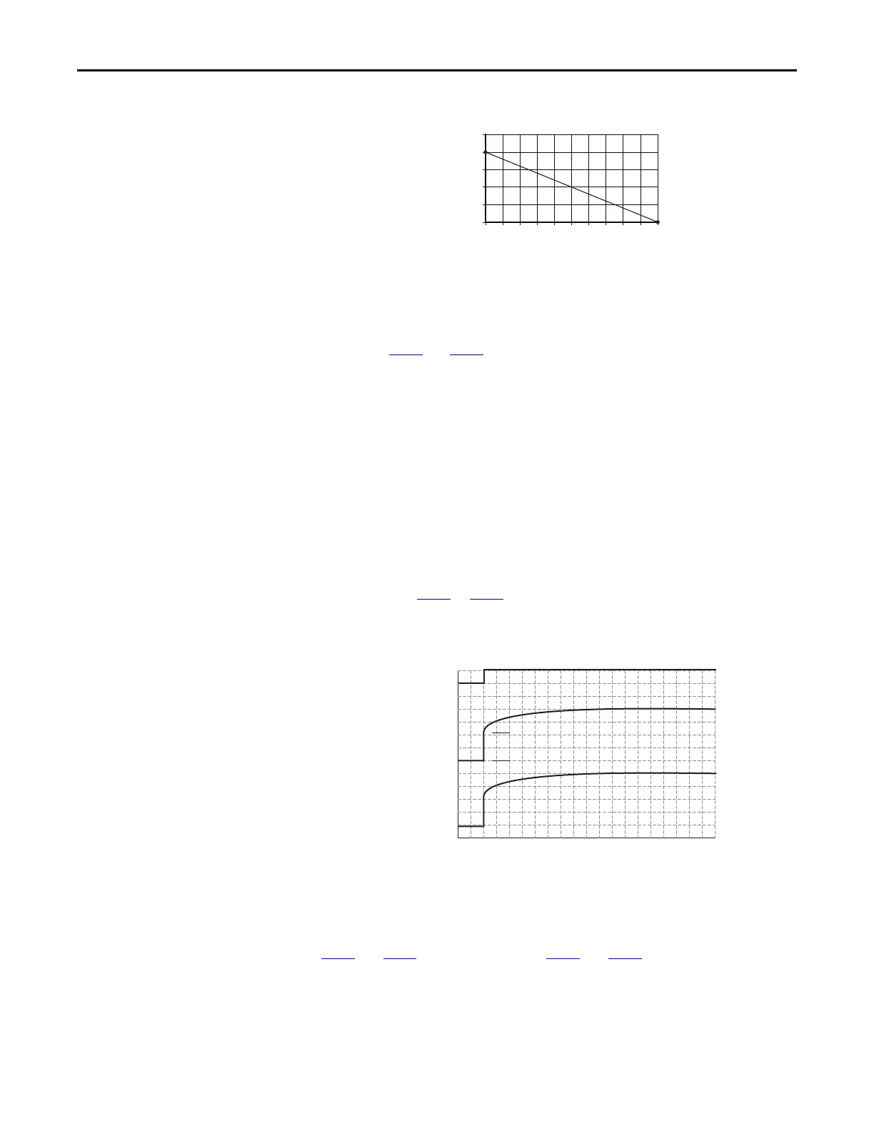
PID Preload
The value set in A466 or A478 [PID x Preload], in Hz, will be pre-loaded into
the integral component of the PID at any start or enable. This will cause the
drive’s frequency command to initially jump to that preload frequency, and the
PID loop starts regulating from there.
PID Limits
A456 and A468 [PID x Trim Hi] and A457 and A469 [PID x Trim Lo] are used
to limit the PID output and are only used in trim mode. [PID x Trim Hi] sets the
maximum frequency for the PID output in trim mode. [PID x Trim Lo] sets the
reverse frequency limit for the PID output in trim mode. Note that when the
0102030405060708090100
PID Reference (%)
4-20 mA Input
4
8
12
16
20
24
PID Enabled
Freq Cmd
PID Output
PID Pre-load Value
PID Pre-load Value > 0

 Loading...


