72 Rockwell Automation Publication 520-UM001G-EN-E - September 2014
Chapter 3 Programming and Parameters
Basic Display Group (continued)
b007 [Fault 1 Code] Related Parameter(s): F604-F610
b008 [Fault 2 Code]
b009 [Fault 3 Code]
A code that represents a drive fault. Codes appear in these parameters in the order they occur (b007
[Fault 1 Code] = the most recent fault). Repetitive faults are only recorded once.
See Fault and Diagnostic Group for more information.
Values Default: Read Only
Min/Max: F0/F127
Display: F0
b010 [Process Display] Related Parameter(s): b001, A481, A482
32 bit parameter.
Output frequency scaled by [Process Disp Hi] and [Process Disp Lo].
Values Default: Read Only
Min/Max: 0/9999
Display: 1
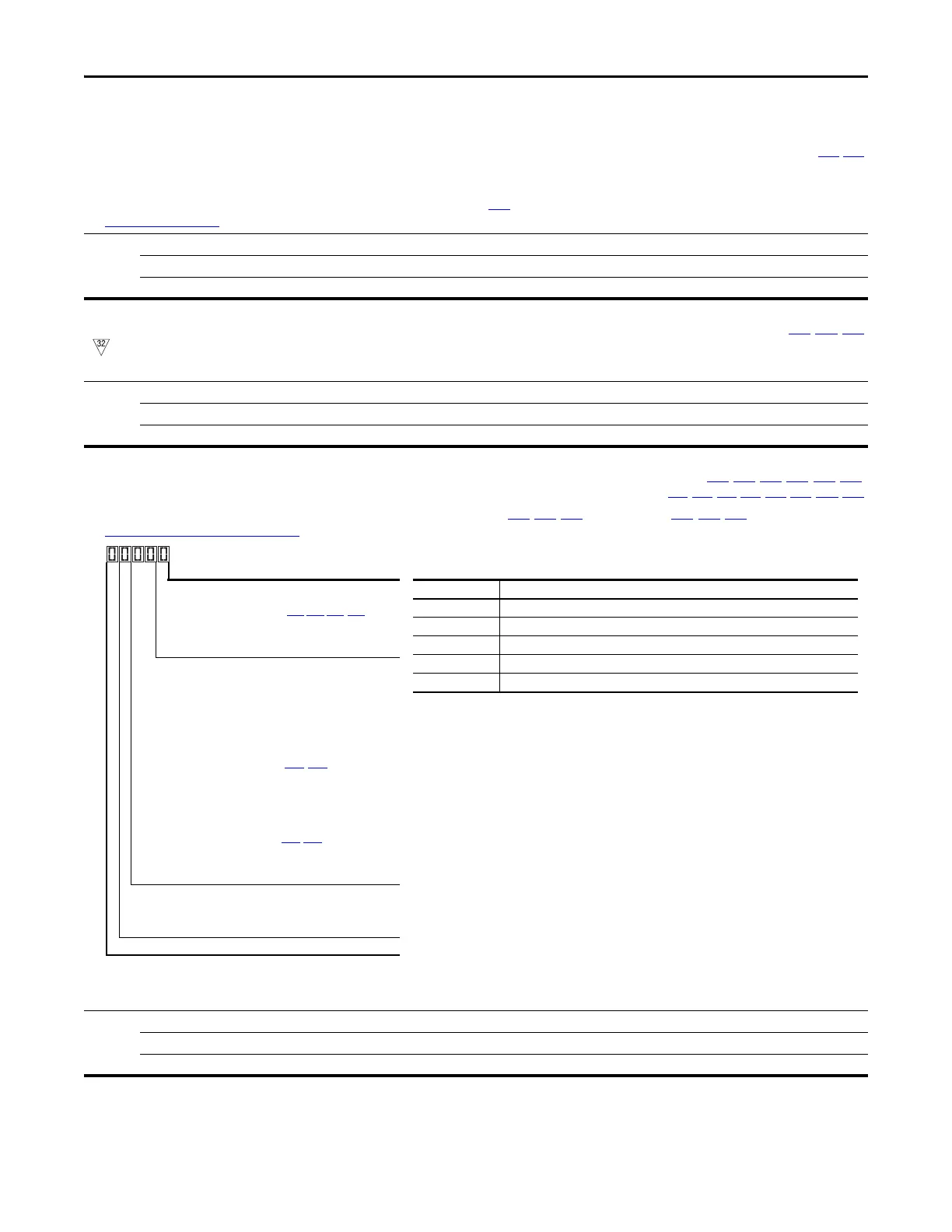
b012 [Control Source] Related Parameter(s): P046, P047, P048, P049, P050, P051,
t062
, t063, t065-t068, L180-L187, A410-A425
Active source of the Start Command and Frequency Command. Normally defined by the settings of P046, P048, P050 [Start Source x] and P047, P049, P051 [Speed Referencex].
See Start and Speed Reference Control on page 46 for more information.
Values Default: Read Only
Min/Max: 0000/2165
Display: 0000
Start Command Source Digit 1
1 = Keypad
2 = DigIn TrmBlk (Parameters t062,t063,t065-t068)
3 = Serial/DSI
4 = Network Opt
(1)
5 = EtherNet/IP
(2)
(1) Select this setting if using the optional PowerFlex 25-COMM-E2P, 25-COMM-D, or
25-COMM-P adapters as the Start source and/or Frequency source.
(2) Setting is specific to PowerFlex 525 drives only.
Frequency Command Source Digit 2 & 3
00 = Other
01 = Drive Pot
02 = Keypad
03 = Serial/DSI
04 = Network Opt
(1)
05 = 0-10V Input
06 = 4-20mA Input
07 = Preset Freq (Parameters A410
-A425)
08 = Anlg In Mult
(2)
09 = MOP
10 = Pulse Input
11 = PID1 Output
12 = PID2 Output
(2)
13 = Step Logic (Parameters L180-L187)
(1)
14 = Encoder
(2)
15 = EtherNet/IP
(2)
16 = Positioning
(2)
Frequency Command Source Digit 4
0 = Other (Digit 2 & 3 are used. Digit 4 is not shown.)
1 = Jog
2 = Purge
Not Used
Display reads... Description
2004 Start source comes from Network Opt and Frequency source is Purge.
113 Start source comes from Serial/DSI and Frequency source comes from PID1 Output.
155 Start source and Frequency source comes from EtherNet/IP.
052 Start source comes from DigIn TrmBlk and Frequency source from 0-10V Input.
011 Start source comes from Keypad and Frequency source comes from Drive Pot.
Example

 Loading...


