Rockwell Automation Publication 520-QS001A-EN-E - March 2014 29
PowerFlex 520-Series Adjustable Frequency AC Drive
Fault Codes
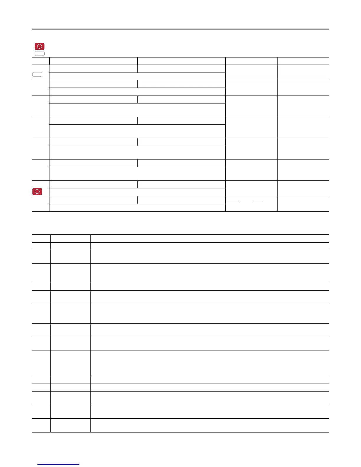
A566 [Pos Reg Gain] 0.0/200.0 0.1 3.0
Sets the gain adjustment for the position regulator.
A567 [Max Traverse] 0.00/300.00 Hz 0.01 Hz 0.00 Hz
Sets the amplitude of triangle wave speed modulation.
A568 [Traverse Inc] 0.00/300.00 s 0.01 s 0.00 s
Sets the time required for the Traverse function to accelerate from the minimum to the maximum traverse
frequency. See the diagram at A567 [Max Traverse].
A569 [Traverse Dec] 0.00/300.00 s 0.01 s 0.00 s
Sets the time required for the Traverse function to decelerate from the maximum to the minimum traverse
frequency. See the diagram at A567 [Max Traverse].
A570 [P Jump] 0.00/300.00 Hz 0.01 Hz 0.00 Hz
Sets the frequency amplitude that is added to or subtracted from the commanded frequency. See the
diagram at A567 [Max Traverse].
A571 [Sync Time] 0.0/3200.0 s 0.1 s 0.0 s
Enables the function that holds the drive at the current frequency even if the commanded frequency
changes. Used with t062, t063, t065-t068 [DigIn TermBlk xx] 32 “Sync Enable”.
A572 [Speed Ratio] 0.01/99.99 0.01 1.00
Scales the drive speed command.
A573 [Mtr Options Cfg] 00/11 Digit 2
Digit 1
ZeroSpd Slip Jerk Select
11
Sets the configuration of the motor option.
No. Fault Action
F000 No Fault –
F002 Auxiliary Input • Check remote wiring.
• Verify communications programming for intentional fault.
F003 Power Loss • Monitor the incoming AC line for low voltage or line power interruption.
• Check input fuses.
• Reduce load.
F004 UnderVoltage Monitor the incoming AC line for low voltage or line power interruption.
F005 OverVoltage Monitor the AC line for high line voltage or transient conditions. Bus overvoltage can also be caused by motor regeneration. Extend the decel time
or install dynamic brake option.
F006 Motor Stalled • Increase P041, A442, A444, A446 [Accel Time x] or reduce load so drive output current does not exceed the current set by parameter A484,
A485 [Current Limit x] for too long.
• Check for overhauling load.
F007 Motor Overload • An excessive motor load exists. Reduce load so drive output current does not exceed the current set by parameter P033 [Motor OL Current].
• Verify A530 [Boost Select] setting.
F008 Heatsink OvrTmp • Check for blocked or dirty heat sink fins. Verify that ambient temperature has not exceeded the rated ambient temperature.
• Check fan.
F009 CC OvrTmp • Check product ambient temperature.
• Check for airflow obstruction.
• Check for dirt or debris.
• Check fan.
F012 HW OverCurrent Check programming. Check for excess load, improper A530 [Boost Select] setting, DC brake volts set too high or other causes of excess current.
F013 Ground Fault Check the motor and external wiring to the drive output terminals for a grounded condition.
F015
(1)
Load Loss • Verify connections between motor and load.
• Verify level and time requirements.
F021 Output Ph Loss • Verify motor wiring.
• Verify motor.
F029 Analog In Loss • Check for broken/loose connections at inputs.
• Check parameters.
= Stop drive before changing this parameter.
= Parameter is specific to PowerFlex 525 drives only.
No. Parameter Min/Max Display/Options Default
PF 525
 Loading...


