EasyManuals Logo

Allen-Bradley PowerFlex 525 Application Technique

Allen-Bradley PowerFlex 525
24 pages
To Next Page IconTo Next Page
To Previous Page IconTo Previous Page
Page #15 background imageLoading...
Page #15 background image
Rockwell Automation Publication SAFETY-AT140A-EN-P - May 2015 15
Safety Function: Actuator Subsystems – Stop Category 1 via the PowerFlex 525 and PowerFlex 527 Drives with Safe Torque-off
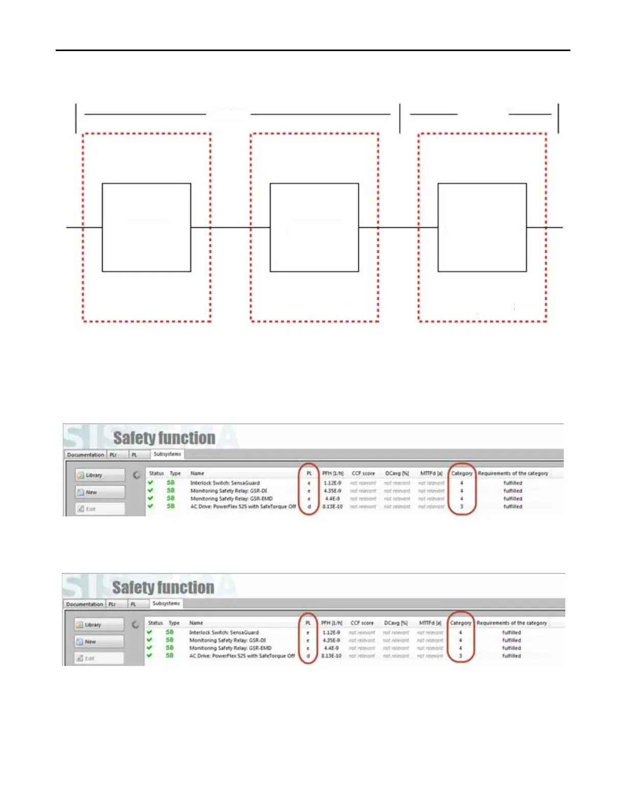
This can be modeled as follows:
The rest of the SISTEMA calculation in this document features a SensaGuard switch as an example of a typical safety input
device.
For instance, when the PowerFlex 525 drive is used, these are the SISTEMA calculations for the safety function, "Safety-
related stop function initiated by a safeguard:"
When the PowerFlex 525 drive is used in the safety function, "Prevention of an unexpected startup," the SISTEMA
calculations are identical, because all of the same components are used.
Logic
Output
Subsystem 1
Subsystem 2
Subsystem 3
Guardmaster
Dual-input
Safety Relay
Guardmaster
Multifunction-delay
Expansion Module
PowerFlex
527 Drive

Other manuals for Allen-Bradley PowerFlex 525

Questions and Answers:

Question and Answer IconNeed help?

Do you have a question about the Allen-Bradley PowerFlex 525 and is the answer not in the manual?

Allen-Bradley PowerFlex 525 Specifications

General IconGeneral
Horsepower0.5-30 HP
kW0.4-22 kW
Input Voltage200-240V AC, 380-480V AC
EnclosureIP20, NEMA/UL Type 1
CommunicationsEtherNet/IP
Control MethodsV/Hz, Sensorless Vector
STOSafe Torque Off (STO)
Output Voltage0-Input Voltage
Operating Temperature-20°C to 50°C (-4°F to 122°F)
Storage Temperature-40°C to 85°C (-40°F to 185°F)
Relative Humidity5-95% non-condensing
DimensionsVaries by model
WeightVaries by model

Related product manuals