Behavior models used in CIP Motion
26 Rockwell Automation Publication MOTION-RM003I-EN-P - February 2018
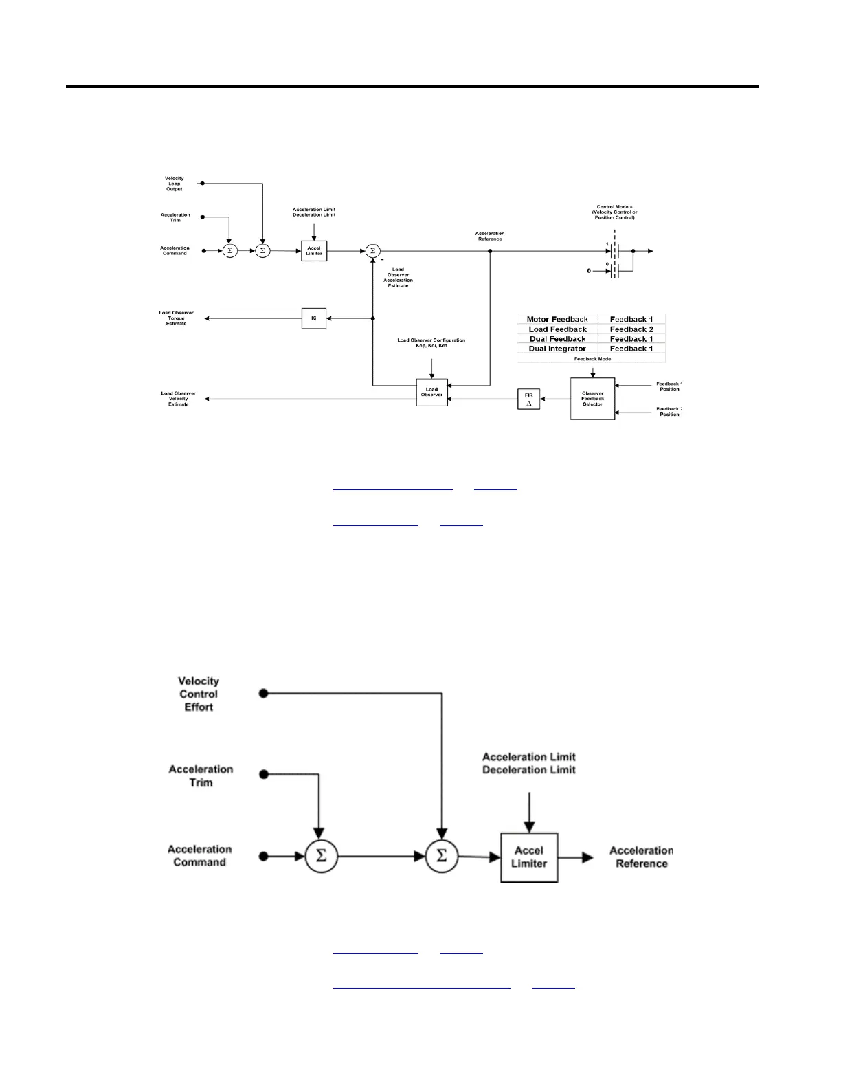
The following diagram provides an overview of the Acceleration Control behavior
model, including the Load Observer.
See also
Acceleration Limiter on page 26
Load Observer on page 27
The output of the acceleration command summing junction signal passes through
a limiter to produce the Acceleration Reference signal. The Accel Limiter applies a
directional acceleration limit, either the Acceleration Limit or the Deceleration
Limit, to the input command signal based on the sign of the signal.
The following diagram illustrates this process.
See also
Load Observer on page 27
Acceleration Control Behavior on page 25
Acceleration Limiter

 Loading...


