446 Rockwell Automation Publication MOTION-RM003I-EN-P - February 2018
the stopping sequences end up in the Major Faulted state. In the context of a
Shutdown Request, the Category 0 stopping method below is applied in the
Stopping state and the stopping sequence ends up in Shutdown state.
Category 0 Stop Sequence
Inverter is immediately disabled. Brake Proving is not applicable.
1. Switch to Stopping state
2. Disable inverter power structure.
3. Deactivate Resistive Brake contactor to disconnect motor from inverter
power structure.
4. Wait for zero speed or "Coasting Time Limit" or a factory set timeout,
whichever occurs first.
5. Transition to Stopped state.
6. Deactivate Mechanical Brake output to engage brake.
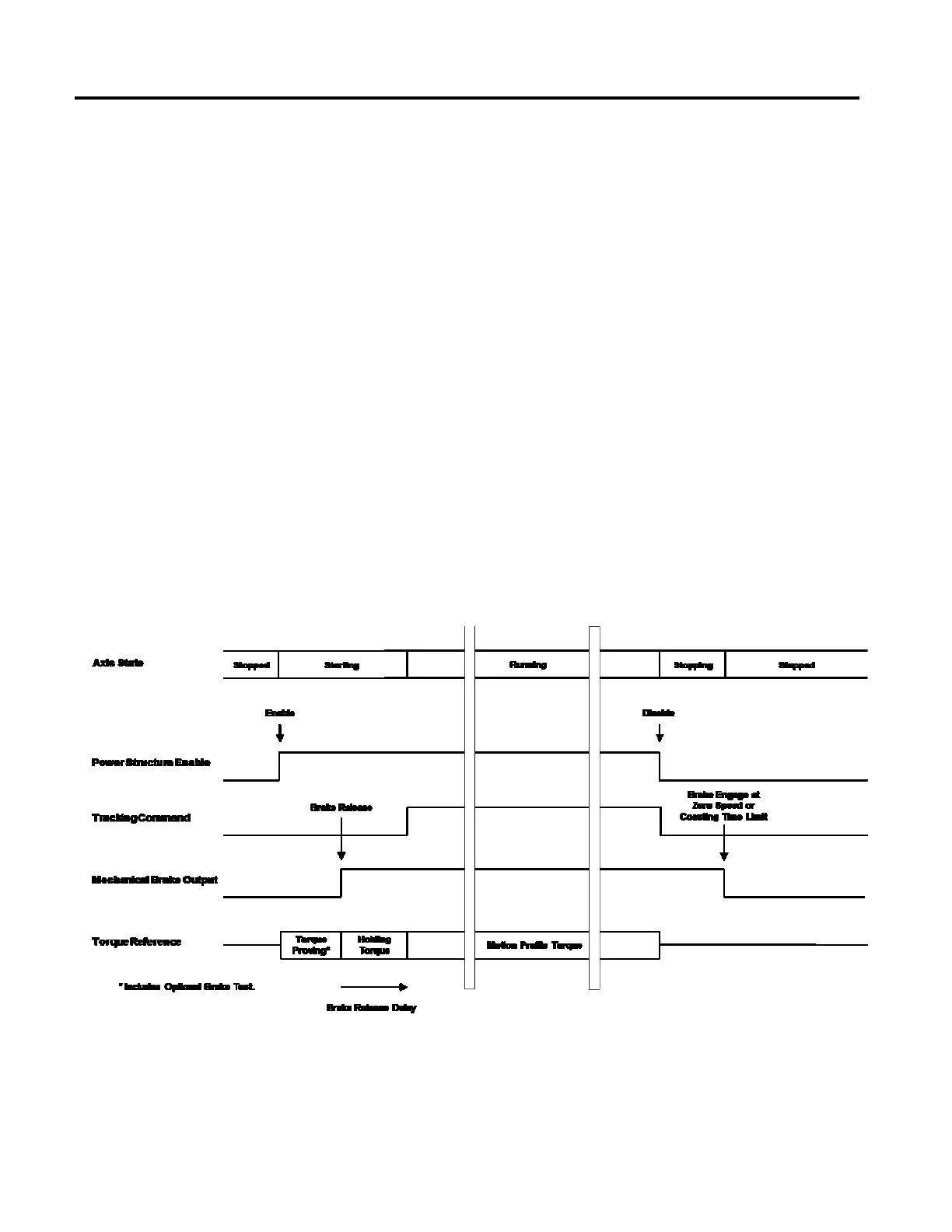
The following diagram illustrates Category 0 Stop Sequence:
Category 1 Stop Sequence
Torque applied to stop the motor before the inverter is disabled. Brake Proving is
applicable.

 Loading...


