Digital Inputs 2-77
The “Bipolar Cflct” alarm will be asserted if both of the following are true:
• One or more of the following digital input functions are configured:
“Forward/Reverse”, “Run Forward”, “Run Reverse”, “Jog Forward”,
“Jog Reverse”.
• [Direction Mode] is set to “Bipolar” or “Reverse Dis”.
Digital In Status
This parameter represents the current state of the digital inputs. It contains
one bit for each input. The bits are “1” when the input is closed and “0”
when the input is open.
Digital In Examples
PowerFlex 70
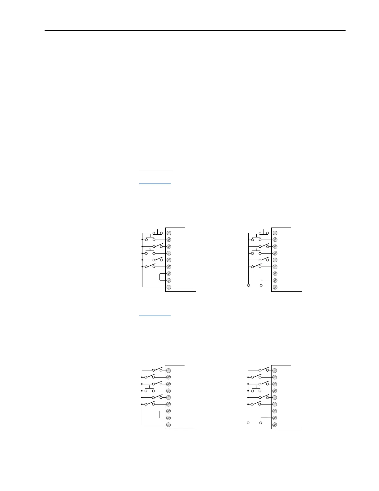
Figure 2.16 shows a typical digital input configuration that includes
“3-wire” start. The digital input configuration parameters should be set as
shown.
Figure 2.16 Typical digital input configuration with “3-wire” start
Figure 2.17 represents a typical digital input configuration that includes
“2-wire” start. The digital input configuration parameters should be set up
as shown
Figure 2.17 Typical digital input configuration with “Run Fwd/Rev” start
Digital In1
Digital In2
Digital In3
Digital In4
Digital In5
Digital In6
24V Common
Digital In Common
24V
= Stop
= Start
= Forward/Reverse
= Jog
= Speed Select 1
= Enable
Digital In1
Digital In2
Digital In3
Digital In4
Digital In5
Digital In6
24V Common
Digital In Common
24V
= Stop
= Start
= Forward/Reverse
= Jog
= Speed Select 1
= Enable
Internal Power Source
+24V Common
External Power Source
Digital In1
Digital In2
Digital In3
Digital In4
Digital In5
Digital In6
24V Common
Digital In Common
24V
= Run
= Clear Faults
= Forward/Reverse
= Jog
= Auxiliary Fault
= Enable
= Run
= Clear Faults
= Forward/Reverse
= Jog
= Auxiliary Fault
= Enable
Digital In1
Digital In2
Digital In3
Digital In4
Digital In5
Digital In6
24V Common
Digital In Common
24V
Internal Power Source
+24V Common
External Power Source

 Loading...


