Speed Control, Mode, Regulation & Vector Speed Feedback 2-167
When the slip compensation mode is selected, the drive calculates an
amount to increase the output frequency to maintain a consistent motor
speed independent of load. The amount of slip compensation to provide is
selected in [Slip RPM @ FLA]. During drive commissioning this parameter
is set to the RPM that the motor will slip when operating with Full Load
Amps. The user may adjust this parameter to provide more or less slip.
As mentioned above, induction motors exhibit slip which is the difference
between the stator electrical frequency, or output frequency of the drive, and
the induced rotor frequency.
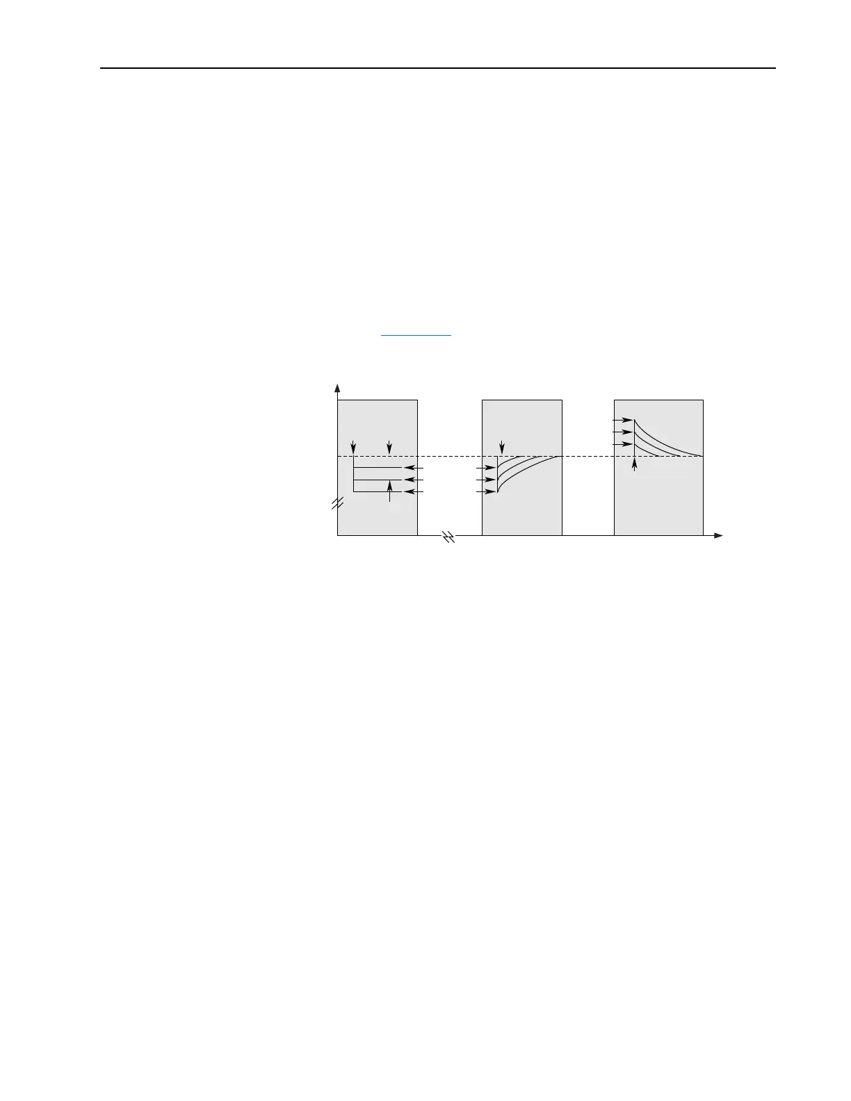
The slip frequency translates into a slip speed resulting in a reduction in
rotor speed as the load increases on the motor. This can be easily seen by
examining Figure 2.32
.
Figure 2.32 Rotor Speed with/without Slip Compensation
Without slip compensation active, as the load increases from no load to
150% of the motor rating, the rotor speed decreases approximately
proportional to the load.
With slip compensation, the correct amount of slip compensation is added
to the drive output frequency based on motor load. Thus, the rotor speed
returns to the original speed. Conversely, when the load is removed, the
rotor speed increases momentarily until the slip compensation decays to
zero.
Motor nameplate data must be entered by the user in order for the drive to
correctly calculate the proper amount of slip compensation. The motor
nameplate reflects slip in the rated speed value at rated load. The user can
enter the Motor Nameplate RPM, Motor Nameplate Frequency, the Motor
Nameplate Current, Motor Nameplate Voltage, and Motor Nameplate HP/
kW and during commissioning the drive calculates the motor rated slip
frequency and displays it in [Slip RPM @ FLA]. The user can adjust the slip
compensation for more accurate speed regulation, by increasing or
decreasing [Slip RPM @ FLA] value.
Slip Compensation
Active
Slip Compensation
Inactive
Time
Rotor Speed
0
0
Load
Applied
Load
Applied
No Load
Slip @
F.L.A.
0.5 p.u. Load
1.0 p.u. Load
1.5 p.u. Load
0.5 p.u. Load
1.0 p.u. Load
1.5 p.u. Load
Slip Compensation
Active
Load
Removed

 Loading...


