EasyManuals Logo

Allen-Bradley powerflex 700 Reference Manual

Allen-Bradley powerflex 700
300 pages
To Next Page IconTo Next Page
To Previous Page IconTo Previous Page
Page #22 background imageLoading...
Page #22 background image
1-14 PowerFlex 700 Dimensions
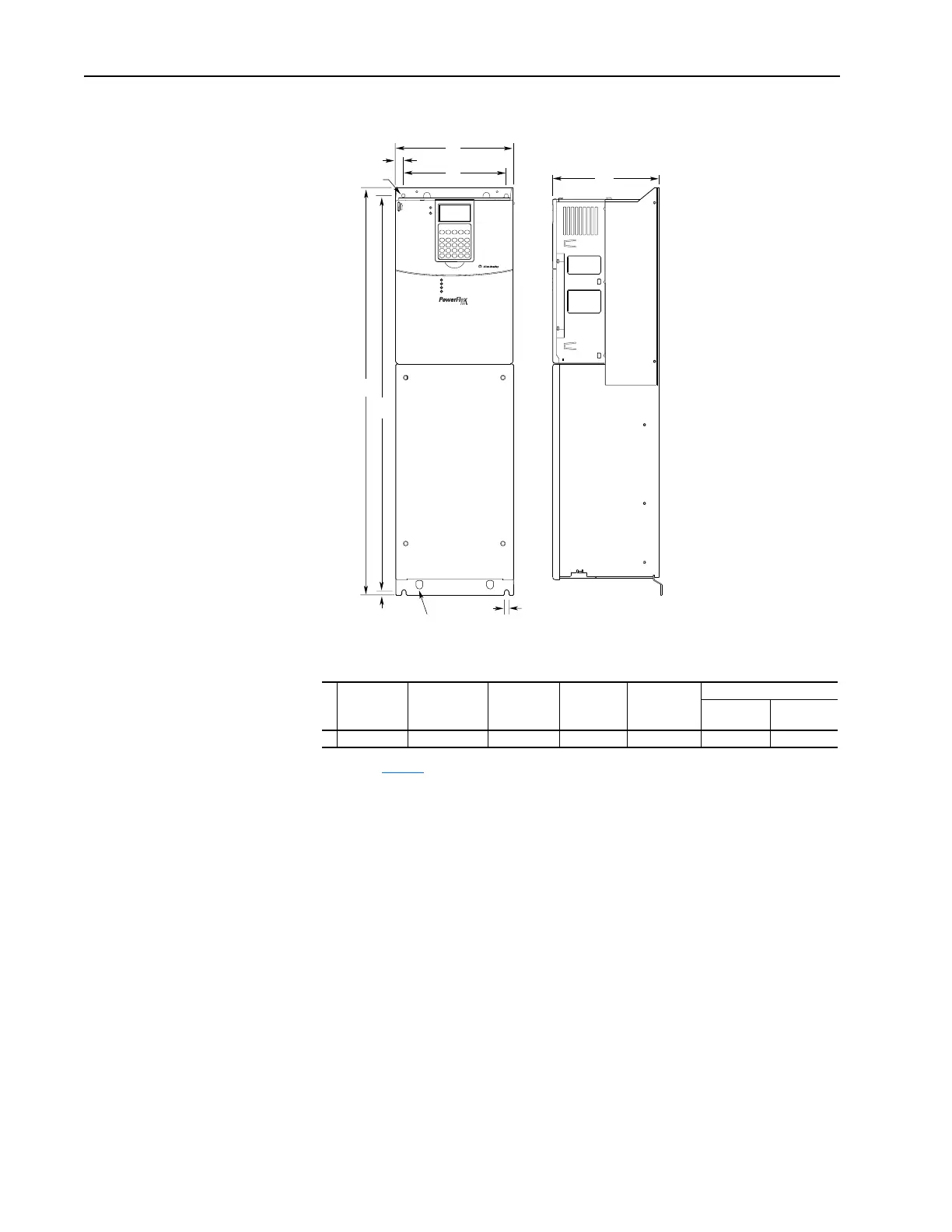
Figure 1.8 PowerFlex 700 Frame 4
Dimensions are in millimeters and (inches)
Frame
(1)
(1)
Refer to Ta ble 1. B for frame information.
A (Max.) BC (Max.) DE
Approx. Weight
(2)
kg (lbs.)
(2)
Weights include HIM and Standard I/O.
Drive
Drive &
Packaging
4 220.0 (8.66) 758.8 (29.87) 201.7 (7.94) 192.0 (7.56) 738.2 (29.06) 24.49 (54.0) 29.03 (64.0)
C
E
8.0
(0.31)
B
7.0 (0.28) dia.
7.0 (0.28)
3 Places
A
D
15.0 (0.59)
Lifting Holes
4 Places

Table of Contents

Other manuals for Allen-Bradley powerflex 700

Questions and Answers:

Question and Answer IconNeed help?

Do you have a question about the Allen-Bradley powerflex 700 and is the answer not in the manual?

Allen-Bradley powerflex 700 Specifications

General IconGeneral
SeriesPowerFlex 700
CategoryAC Drive
Input Voltage200-240V AC, 380-480V AC, 500-600V AC
EnclosureType 1
Control MethodSensorless Vector
CommunicationEtherNet/IP, ControlNet, DeviceNet, PROFIBUS DP, Modbus

Related product manuals