EasyManuals Logo

Allen-Bradley powerflex 700 Reference Manual

Allen-Bradley powerflex 700
300 pages
To Next Page IconTo Next Page
To Previous Page IconTo Previous Page
Page #23 background imageLoading...
Page #23 background image
PowerFlex 700 Dimensions 1-15
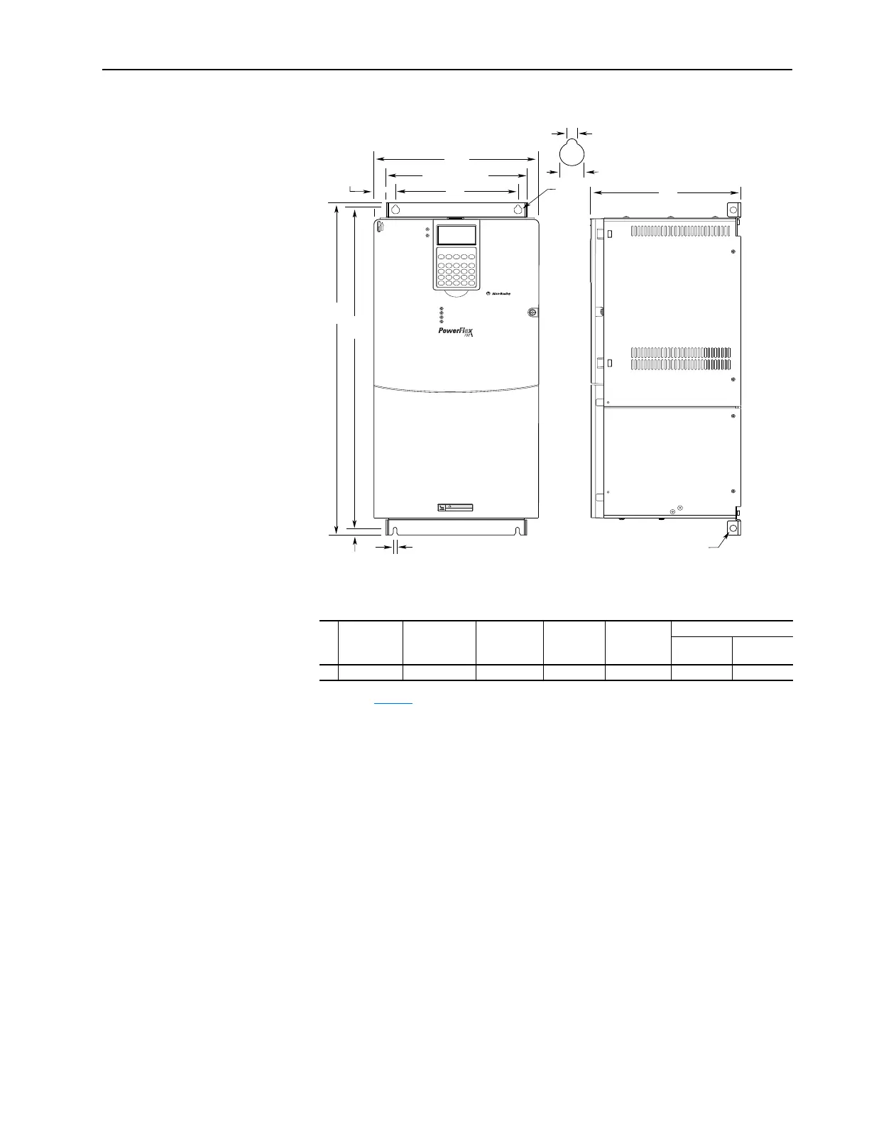
Figure 1.9 PowerFlex 700 Frame 5
Dimensions are in millimeters and (inches).
Frame
(1)
(1)
Refer to Ta ble 1. B for frame information.
A (Max.) BC (Max.) DE
Approx. Weight
(3)
kg (lbs.)
(3)
Weights include HIM and Standard I/O.
Drive
Drive &
Packaging
5 308.9 (12.16) 644.5 (25.37)
(2)
(2)
When using the supplied junction box (100 HP drives Only), add an additional 45.1 mm (1.78 in.) to this
dimension.
275.4 (10.84) 225.0 (8.86) 625.0 (24.61) 37.19 (82.0) 42.18 (93.0)
HOT surfaces can cause severe burns
CAUTION
E
12.5
(0.49)
6.5 (0.26)
B
D
A
259.1 (10.20)
Detail
15.0 (0.59)
6.5 (0.26)
37.6 (1.48)
C
Lifting Holes - 4 Places
12.7 (0.50) Dia.

Table of Contents

Other manuals for Allen-Bradley powerflex 700

Questions and Answers:

Question and Answer IconNeed help?

Do you have a question about the Allen-Bradley powerflex 700 and is the answer not in the manual?

Allen-Bradley powerflex 700 Specifications

General IconGeneral
SeriesPowerFlex 700
CategoryAC Drive
Input Voltage200-240V AC, 380-480V AC, 500-600V AC
EnclosureType 1
Control MethodSensorless Vector
CommunicationEtherNet/IP, ControlNet, DeviceNet, PROFIBUS DP, Modbus

Related product manuals