EasyManuals Logo

Allen-Bradley powerflex 700 Reference Manual

Allen-Bradley powerflex 700
300 pages
To Next Page IconTo Next Page
To Previous Page IconTo Previous Page
Page #273 background imageLoading...
Page #273 background image
Evaluating the Internal Resistor 3-9
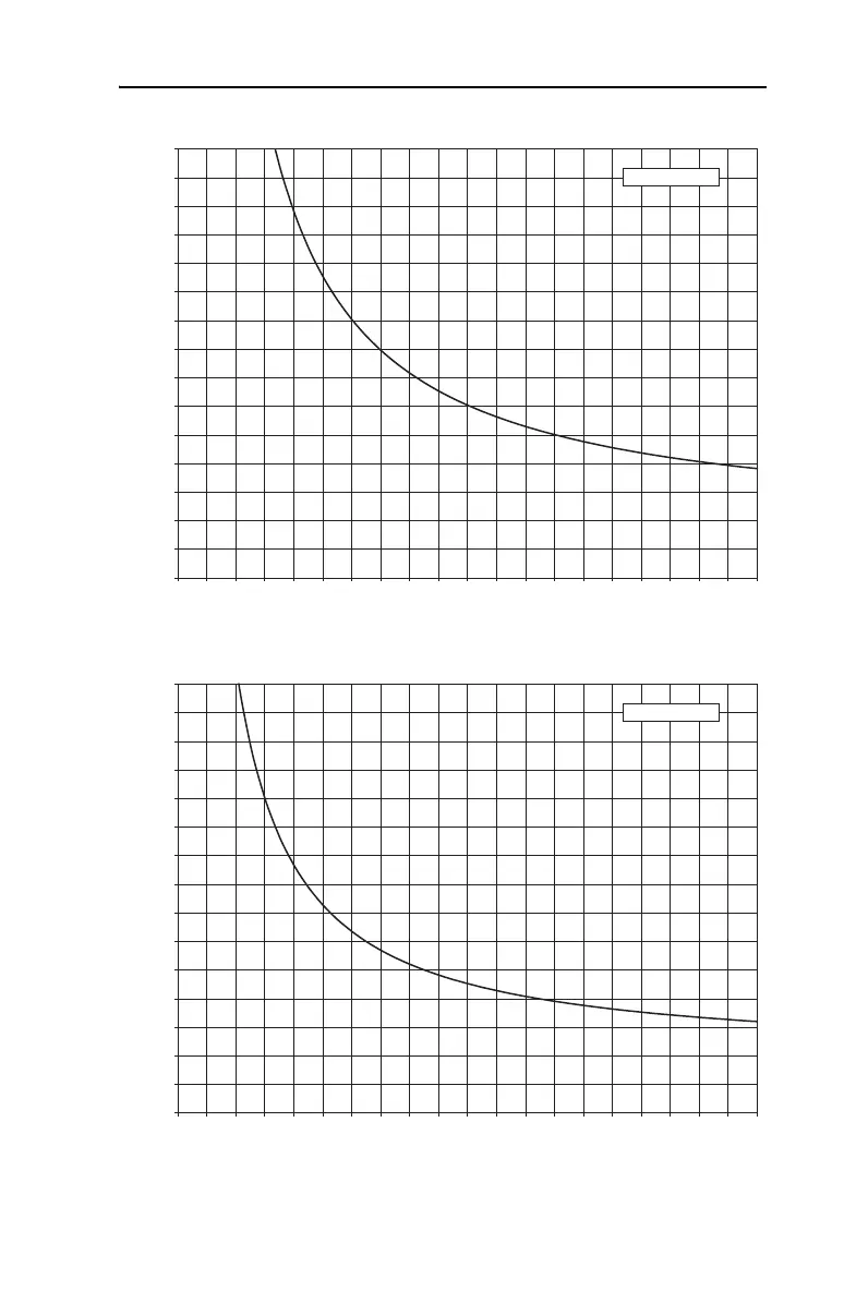
Figure 3.12 PowerFlex 700 – 240 Volt, Frame 2
Figure 3.13 PowerFlex 700 – 480 Volt, Frame 0
0
200
400
600
800
1000
1200
1400
1600
1800
2000
2200
2400
2600
2800
3000
0 1 2 3 4 5 6 7 8 9 10 11 12 13 14 15 16 17 18 19 20
240V Frame 2
Decel Time (Seconds)
% Peak Power
0
200
400
600
800
1000
1200
1400
1600
1800
2000
2200
2400
2600
2800
3000
0 1 2 3 4 5 6 7 8 9 10 11 12 13 14 15 16 17 18 19 20
400V Frame 0
Decel Time (Seconds)
% Peak Power

Table of Contents

Other manuals for Allen-Bradley powerflex 700

Questions and Answers:

Question and Answer IconNeed help?

Do you have a question about the Allen-Bradley powerflex 700 and is the answer not in the manual?

Allen-Bradley powerflex 700 Specifications

General IconGeneral
SeriesPowerFlex 700
CategoryAC Drive
Input Voltage200-240V AC, 380-480V AC, 500-600V AC
EnclosureType 1
Control MethodSensorless Vector
CommunicationEtherNet/IP, ControlNet, DeviceNet, PROFIBUS DP, Modbus

Related product manuals