2-50 Bus Regulation
Table 2.C
If [Bus Reg Mode A], parameter 161 is set to “Dynamic Brak”
The Dynamic Brake Regulator is enabled. In “Dynamic Brak” mode the
Bus Voltage Regulator is turned off. The “DB Turn On” and turn off curves
apply (Table 2.C
). For example, with a DC Bus Memory at 684V DC, the
Dynamic Brake Regulator will turn on at 750V DC and turn back off at
742V DC.
If [Bus Reg Mode A], parameter 161 is set to “Both-Frq 1st”
Both regulators are enabled, and the operating point of the Bus Voltage
Regulator is lower than that of the Dynamic Brake Regulator. The Bus
Voltage Regulator setpoint follows the “Bus Reg Curve 2” below a DC Bus
Memory of 650V DC and follows the “DB Turn Off” curve above a DC Bus
Memory of 650V DC (Table 2.D
). The Dynamic Brake Regulator follows
the “DB Turn On” and turn off curves (Table 2.C
). For example, with a DC
Bus Memory at 684V DC, the Bus Voltage Regulator setpoint is 742V DC
and the Dynamic Brake Regulator will turn on at 750V DC and back off at
742V DC.
If [Bus Reg Mode A], parameter 161 is set to “Adjust Freq”
The Bus Voltage Regulator is enabled. The Bus Voltage Regulator setpoint
follows “Bus Reg Curve 1” below a DC Bus Memory of 650V DC and
follows the “DB Turn On” above a DC Bus Memory of 650V DC (Table
2.D). For example, with a DC Bus Memory at 684V DC, the adjust
frequency setpoint is 750V DC.
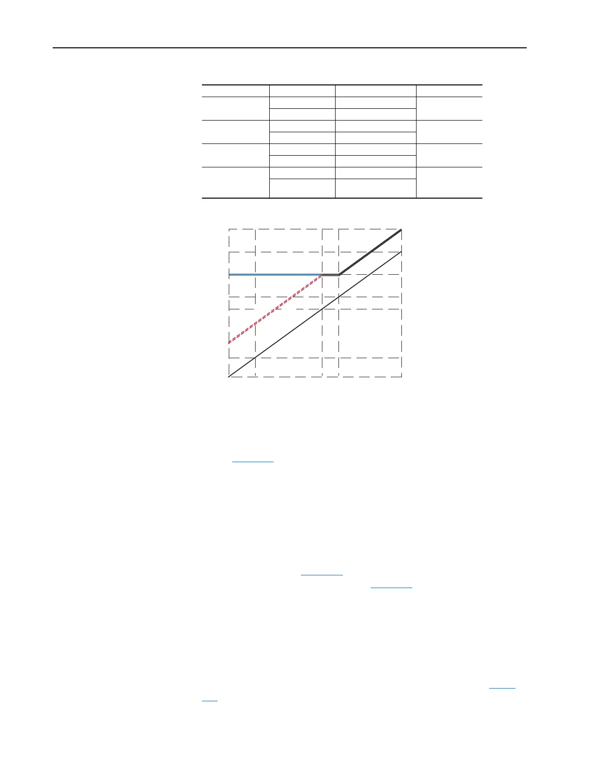
Voltage Class DC Bus Memory DB On Setpoint DB Off Setpoint
240 < 342V DC 375V DC On – 4V DC
> 342V DC Memory + 33V DC
480 < 685V DC 750V DC On – 8V DC
> 685V DC Memory + 65V DC
600 < 856V DC 937V DC On – 10V DC
> 856V DC Memory + 81V DC
600/690V
PowerFlex 700
Frames 5 & 6 Only
< 983V DC 1076V DC On – 11V DC
> 983V DC Memory + 93V DC
320 360 460 484 528 576
453
509
650
685
750
815
880
AC Volts
DC Volts
DB Turn On
DB Turn Off
Bus Memory
Bus Reg Curve #2
Bus Reg Curve #1

 Loading...


