PowerFlex 700 Technical Data
22 20B-TD001F-EN-P
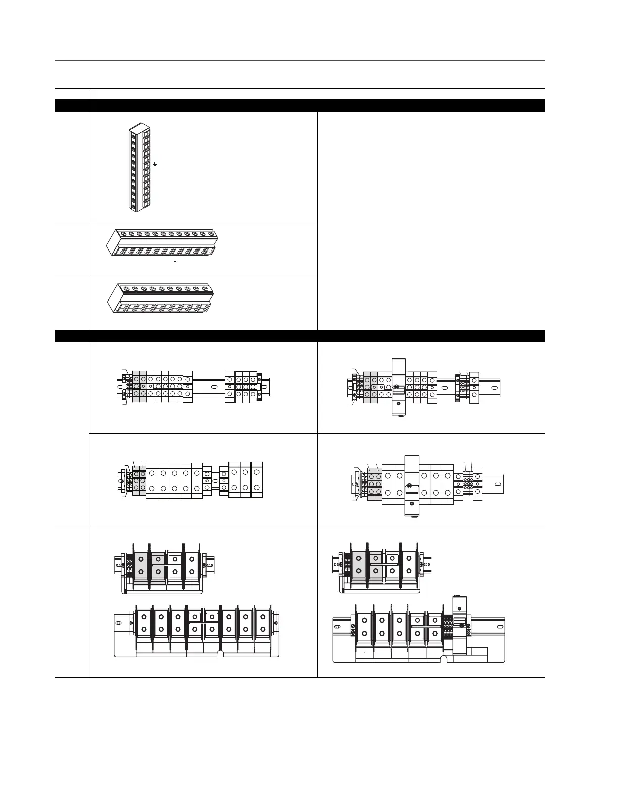
Power Terminals
Frame Terminal Block
0 & 1
* Note:
Shaded BR1 & BR2 Terminals will only be present on drives ordered with the
Brake Option.
2
3 & 4
AC Input DC Input
5 75 Hp, Normal Duty 75 Hp, Normal Duty
100 Hp, Normal Duty 100 Hp, Normal Duty
6 125…200 Hp, Normal Duty 125…200 Hp, Normal Duty
BR1
BR2
DC+
DC–
PE
U (T1)
V (T2)
W (T3)
R (L1)
S (L2)
T (L3)
T
(L3)
S
(L2)
R
(L1)
W
(T3)
V
(T2)
U
(T1)
PEDC–DC+BR2BR1
T
(L3)
S
(L2)
R
(L1)
W
(T3)
V
(T2)
U
(T1)
DC–DC+BR2BR1
T/L3S/L2R/L1PEPEW/T3
V/T2
U/T1
DC–
DC+
BR1*/
DC+
BR2*
PS–
PS+
240
VAC
120
VAC
0
VAC
PE PEW/T3V/T2U/T1DC–DC+
BR1*/
DC+
BR2*
PS–
PS+
T/L3S/L2R/L1
PEPE
W/T3V/T2U/T1DC–DC+
BR1*/
DC+
BR2*
PS–
PS+
240
VAC
120
VAC
0
VAC
PE
PE
W/T3V/T2U/T1DC–DC+
BR1*/
DC+
BR2*
PS–
PS+
USE 75 C
COPPER WIRE
ONLY
TORQUE
52 IN-LB
(6 N-M)
U
T1
DC–DC+BR1BR2
V
T2
W
T3
R
L1
S
L2
INPUTOUTPUT
T
L3
PE PE
USE 75 C COPPER WIRE ONLY, TORQUE 52 IN-LB (6 N-M)
22-10
AWG
5.3 IN-LB
(0.6 N-M)
WIRE STRIP
PS+
PS–
DC–DC+BR1BR2
USE 75 C COPPER WIRE ONLY, TORQUE 52 IN-LB (6 N-M)
22-10
AWG
5.3 IN-LB
(0.6 N-M)
WIRE STRIP
PS+
PS–
U
T1
V
T2
W
T3
PE PE
USE 75 C
COPPER WIRE
ONLY
TORQUE
52 IN-LB
(6 N-M)
OUTPUT
22-10 AWG
5.3 IN-LB
(0.6 N-M)
FAN
INPUT
1-PHASE
0 VAC
120 VAC
240 VAC

 Loading...


