PowerFlex 700 Technical Data
20B-TD001F-EN-P 17
Installation Considerations
Power Wiring
The PowerFlex 700 has the following built in protective features to help simplify installation:
• Ground fault protection during start up and running ensures reliable operation
• Electronic motor overload protection increases motor life
• Removable MOV to ground and common mode capacitors to ground ensure compatibility with ungrounded systems.
These devices must be disconnected if the drive is installed on a resistive grounded distribution system, an ungrounded
distribution system, a B phase grounded distribution system or impedance grounded system. These devices must also
be disconnected if the drive power source is a regenerative unit (such as a bus supply and brake) or is DC fed from an
active converter.
• 6 kV transient protection provides increased robustness for 380…480V system voltages
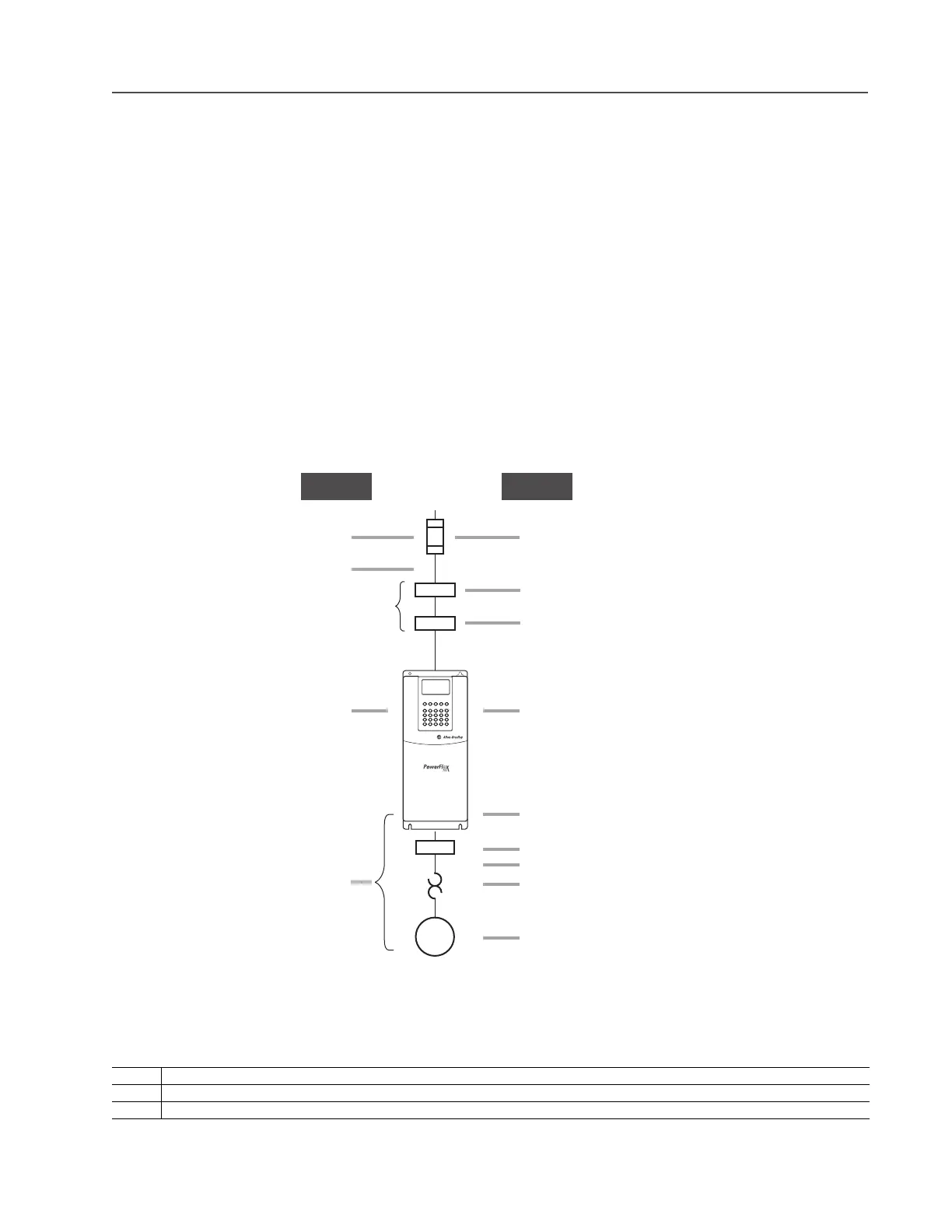
There are many other factors that must be considered for optimal performance in any given application. The block
diagram below highlights the primary installation considerations. Consult Wiring and Grounding Guidelines for AC
Drives (publication DRIVES-IN001) available online at www.rockwellautomation.com/literature, for detailed
recommendations on input power conditioning, dynamic braking, reflected wave protection and motor cable types.
Single-Phase Input Power
The PowerFlex 700 drive is typically used with a three-phase input supply. However, single-phase operation is possible for
certain frames as explained below:
Frame Condition
0…7 Listed by UL to operate on single-phase input power with the requirement that the output current is derated by 50% of the three-phase ratings (see page 32).
8…10 Not designed for single-phase operation.
DC Input AC Input
Not Used
Branch Circuit Protective Devices - Page 32
Input Power Conditioning - Page 10
EMC Requirements - See PowerFlex 700 User Manual
LCD Human Interface Module - Page 7
Reflected Wave Reduction - Page 7
Cable Requirements - Page 31
Integral Class 10 Motor Overload
Motor Recommendations - See Publication MOTORS-CA001
Removable MOV and Caps (underneath cover) - See
PowerFlex 700 User Manual for locations and instructions
Input Fuses - Page 32
Input Cable Length - Page 40
Same as AC
Same as AC

 Loading...


