PowerFlex 700 Technical Data
18 20B-TD001F-EN-P
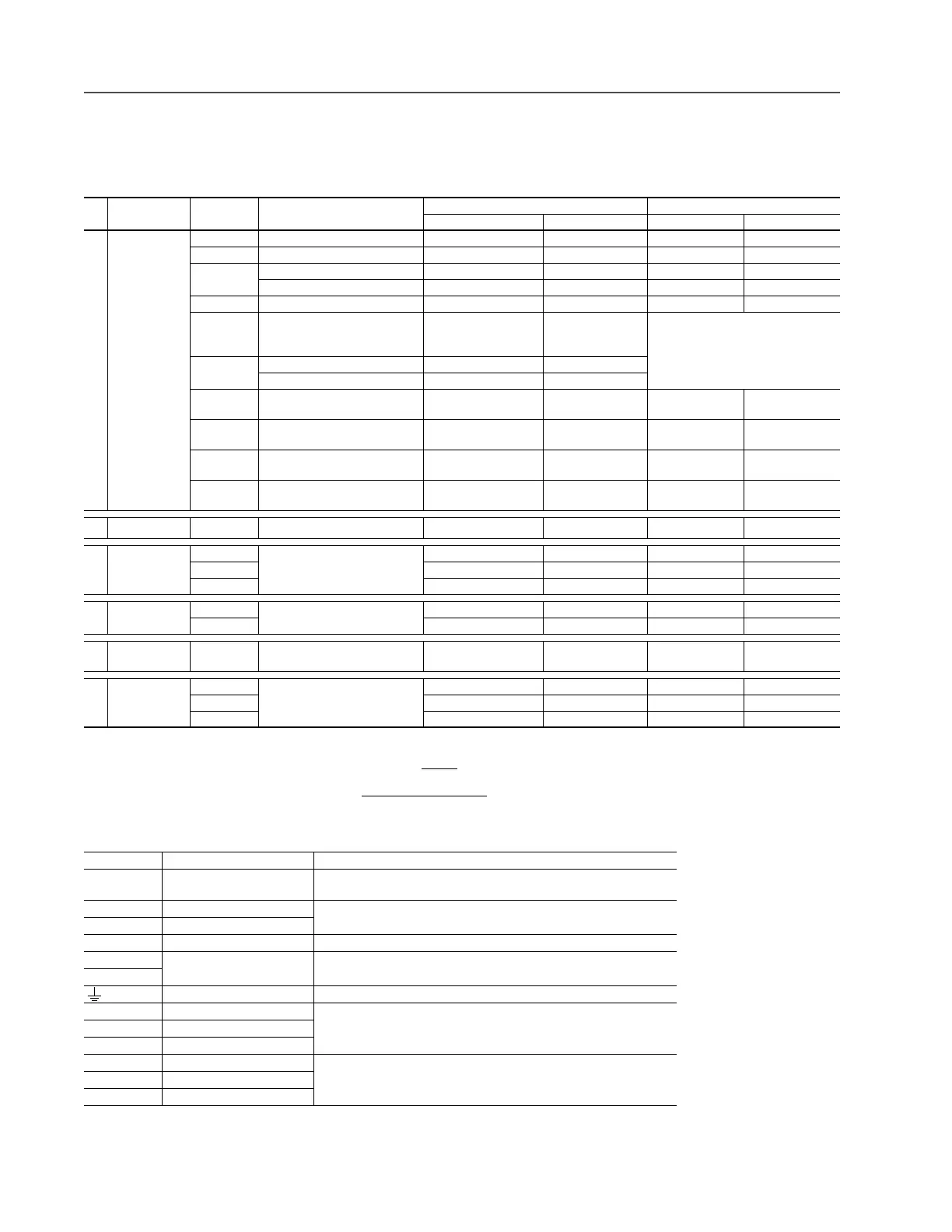
Terminal Blocks
Terminal Block Specifications
Refer to pages 19 and 20 for typical locations.
No. Name Frame Description
Wire Size Range - See Note
(3)
(3)
Maximum/minimum sizes that the terminal block will accept - these are not recommendations.
Torque
Maximum Minimum Maximum Recommended
➊
Power Terminal
Block
0 & 1 Input power and motor connections 4.0 mm
2
(12 AWG) 0.5 mm
2
(22 AWG) 1.7 N•m (15 lb.•in.) 0.8 N•m (7 lb.•in.)
2 Input power and motor connections 10.0 mm
2
(8 AWG) 0.8 mm
2
(18 AWG) 1.7 N•m (15 lb.•in.) 1.4 N•m (12 lb.•in.)
3 Input power and motor connections 25.0 mm
2
(3 AWG) 2.5 mm
2
(14 AWG) 3.6 N•m (32 lb.•in.) 1.8 N•m (16 lb.•in.)
BR1, 2 terminals 10.0 mm
2
(8 AWG) 0.8 mm
2
(18 AWG) 1.7 N•m (15 lb.•in.) 1.4 N•m (12 lb.•in.)
4 Input power and motor connections 35.0 mm
2
(1 AWG) 10.0 mm
2
(8 AWG) 4.0 N•m (35 lb.•in.) 4.0 N•m (35 lb.•in.)
5
75Hp, 480V
100Hp, 600V
Input power, DC+, DC–, BR1, 2,
PE, motor connections
50.0 mm
2
(1/0 AWG) 4.0 mm
2
(12 AWG)
See Note
(5)
(5)
Refer to the terminal block label inside the drive.
5
100Hp
Input power, DC+, DC– and motor 70.0 mm
2
(2/0 AWG) 10.0 mm
2
(8 AWG)
BR1, 2, PE terminals 50.0 mm
2
(1/0 AWG) 4.0 mm
2
(12 AWG)
6 Input power, DC+, DC–, BR1, 2,
PE, motor connections
150.0 mm
2
(300 MCM)
see Note
(4)
2.5 mm
2
(14 AWG) 6.0 N•m (52 lb.•in.) 6.0 N•m (52 lb.•in.)
7 Input power, DC+, DC–, PE, motor
connections
150.0 mm
2
(300 MCM)
see Note
(4)
(4)
If may be necessary to connect multiple wires in parallel to these terminals using multiple lugs.
2.5 mm
2
(14 AWG) 2.7 N•m (24 lb.•in.) 2.7 N•m (24 lb.•in.)
8 & 9 Input power, DC+, DC–, PE, motor
connections
300.0 mm
2
(600 MCM)
see Note
(4)
2.5 mm
2
(14 AWG) 10.0 N•m (87 lb.•in.) 10.0 N•m (87 lb.•in.)
10 Input power, DC+, DC–, PE, motor
connections
300.0 mm
2
(600 MCM)
see Note
(4)
2.5 mm
2
(14 AWG) 10.0 N•m (87 lb.•in.) 10.0 N•m (87 lb.•in.)
➋
SHLD Terminal 0…6 Terminating point for wiring shields — — 1.6 N•m (14 lb.•in.) 1.6 N•m (14 lb.•in.)
➌
AUX Terminal
Block
0…4 Auxiliary Control Voltage
PS+, PS–
(1)(2)
(1)
External control power: UL Installation-300V DC, ±10%, Non UL Installation-270…600V DC, ±10% (0…3 Frame-40W, 165 mA, 5 Frame-80W, 90 mA).
(2)
An Auxiliary Control Power Supply such as the 20-24V-AUX can be used with 400/480 and 600/690 Volt drives with Vector Control. However, consult the factory before using an auxiliary
power supply in these instances. Important: The Auxiliary Control Power Supply Must Not
be used with any Standard Control drive or any 200/240V PowerFlex 700 drive, Standard or
Vector Control.
1.5 mm
2
(16 AWG) 0.2 mm
2
(24 AWG) — —
5…6 4.0 mm
2
(12 AWG) 0.5 mm
2
(22 AWG) 0.6 N•m (5.3 lb.•in.) 0.6 N•m (5.3 lb.•in.)
7…10 4.0 mm
2
(12 AWG) 0.049 mm
2
(30 AWG) 0.6 N•m (5.3 lb.•in.) 0.6 N•m (5.3 lb.•in.)
➍
I/O Terminal
Block
0…6 Signal & control connections 2.5 mm
2
(14 AWG) 0.30 mm
2
(22 AWG) 0.6 N•m (5.3 lb.•in.) 0.6 N•m (5.3 lb.•in.)
7…10 4.0 mm
2
(12 AWG) 0.049 mm
2
(30 AWG) 0.6 N•m (5.3 lb.•in.) 0.6 N•m (5.3 lb.•in.)
➎
Encoder
Terminal Block
0…10 Encoder power & signal
connections
0.75 mm
2
(18 AWG) 0.196 mm
2
(24 AWG) 0.6 N•m (5.3 lb.•in.) 0.6 N•m (5.3 lb.•in.)
➏
Fan Terminal
Block
5…6 User Supplied Fan Voltage 4.0 mm
2
(12 AWG) 0.5 mm
2
(22 AWG) 0.6 N•m (5.3 lb.•in.) 0.6 N•m (5.3 lb.•in.)
74.0 mm
2
(12 AWG) 0.5 mm
2
(22 AWG) 0.9 N•m (8.0 lb.•in.) 0.6 N•m (5.3 lb.•in.)
8…10 4.0 mm
2
(12 AWG) 0.5 mm
2
(22 AWG) 0.6 N•m (5.3 lb.•in.) 0.6 N•m (5.3 lb.•in.)
Terminal Description Notes
BR1
BR2
DC Brake (+)
DC Brake (–)
DB Resistor Connection - Important: Only one DB resistor can be used with
Frames 0…3. Connecting an internal & external resistor could cause damage.
DC+ DC Bus (+) DC Input/Brake Connections
DC– DC Bus (–)
PE PE Ground
PS+ Auxiliary Control Terminal Block see page 19
PS–
Motor Ground
U U (T1) To Motor
VV (T2)
WW (T3)
R R (L1) AC Line Input Power
Three-Phase = R, S & T
Single-Phase = R & S Only
(1)
(1)
Frames 0…7 only.
SS (L2)
T T (L3)

 Loading...


