54 Rockwell Automation Publication 750-RM003A-EN-P - April 2018
Chapter 1 Selection Considerations
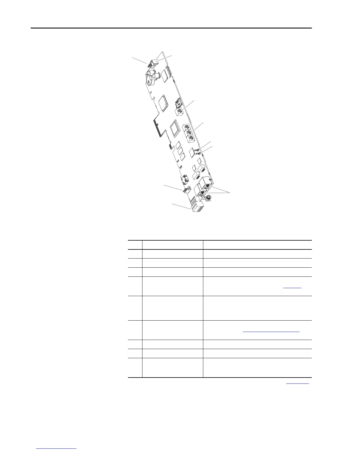
Figure 8 - PowerFlex 755TM Bus Supply Main Control Board I/O and Jumper Locations
Table 26 - Main Control Board Details
Item Name Description
1 HIM Connector DPI Port 01 (HIM Cradle) connection.
2 Fan Connector Power supply for internal cooling fan.
3 Control Selector Rotary switch for setting the programming mode.
4 Embedded EtherNet/IP
(1)
Address
Selectors
(1) Refer to the PowerFlex Drives with TotalFORCE Control Built-in EtherNet/IP Adapter User Manual, publication 750COM-UM009
for detailed configuration information.
Rotary switches for setting lowest octet of EtherNet/IP address
(forces address to 192.168.1.xxx). See publication 750-PM100 for
instructions on setting the IP address.
5 SAFETY Jumper Safety enable jumper. Removed when safety option is installed.
Safety option modules do not function with line side converter, so
this jumper must be installed if this is a line side converter
hardware configuration.
6 ENABLE Jumper Hardware enable jumper. TB1 becomes an Enable when this
jumper is removed. See Hardware Enable Circuits
on page 55 for
more information.
7 Built-in EtherNet/IP
(1)
Connectors Network cable connections.
8 TB1 I/O terminal block.
9 DPI Port 2 DPI Port 02, cable connection to 8-pin round mini-DIN chassis-
mounted connector. Mini-DIN connector that is used for handheld/
remote HIM option and 1203-USB connections.

 Loading...


