EasyManuals Logo

Allen-Bradley PowerFlex 750 Series Installation Instructions

Allen-Bradley PowerFlex 750 Series
32 pages
To Next Page IconTo Next Page
To Previous Page IconTo Previous Page
Page #24 background imageLoading...
Page #24 background image
24 Rockwell Automation Publication 750-IN105D-EN-P - June 2018
PowerFlex 750-Series Service Cart and DC Precharge Module Lift
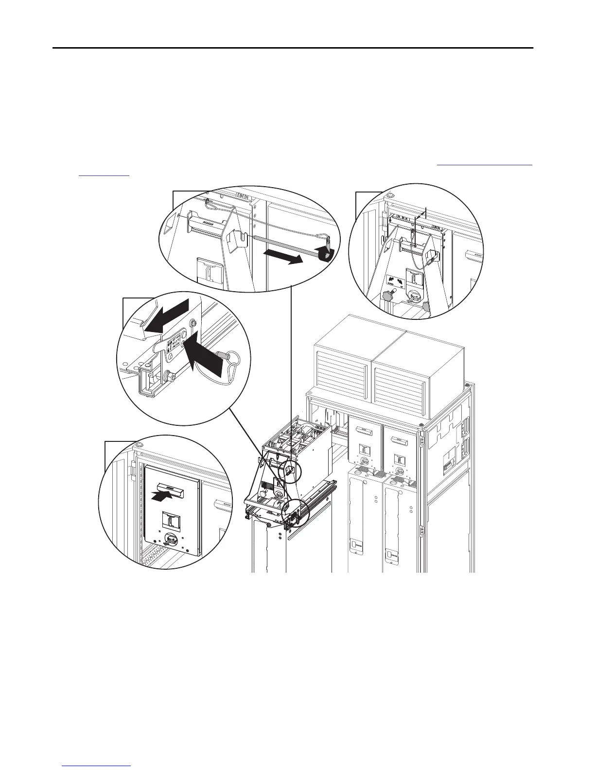
4. With the DC precharge module is approximately 2 inches (50 mm) from the cabinet, loosen the leveling knobs.
5. Remove the locking bar.
6. Retract the carriage.
a. Slide the carriage to the auto-lock position.
b. Insert the locking pin and locking bar.
7. Push the DC precharge module the remaining distance into the control cabinet.
8. If the DCPC module lift is no longer needed, it can be removed from the power module and service cart. See
Remove the DCPC Module
Lift on page 19.
5
6
7
50.8 mm
50.8 mm
(2.0 in)
(2.0 in)
4
a
b

Other manuals for Allen-Bradley PowerFlex 750 Series

Questions and Answers:

Question and Answer IconNeed help?

Do you have a question about the Allen-Bradley PowerFlex 750 Series and is the answer not in the manual?

Allen-Bradley PowerFlex 750 Series Specifications

General IconGeneral
BrandAllen-Bradley
ModelPowerFlex 750 Series
CategoryController
LanguageEnglish

Related product manuals