Rockwell Automation Publication 750-IN105D-EN-P - June 2018 25
PowerFlex 750-Series Service Cart and DC Precharge Module Lift
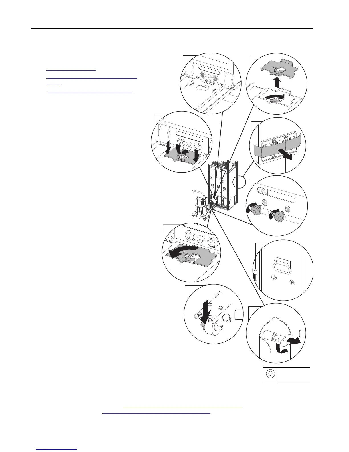
Install the Power Module
Complete these procedures before you install the power
module.
•
Required Tools on page 4
•
Load a Power Module Into the Service Cart on
page 21
•
Install the DC Precharge Module on page 22 (Only
for DC precharge)
Before you install the power module, all applicable safety
guards, anchor bolts, and wire harnesses are disconnected or
removed. The service cart is anchored to the control cabinet
with a power module secured, and where it applies, the DC
precharge module is installed in the cabinet. Follow the
steps below to install a power module.
1. For new module installation, remove the masking
film from the stab busbars on the rear of the power
module.
2. To align with the cabinet floor and track, adjust the
height of the service cart.
If the carriage trolley was marked during module
removal, use that mark for your height reference.
3. Dock service cart to cabinet.
a. Remove the tie-in plate.
b. Connect the bridge span to the cabinet floor.
c. Insert the tie-in plate.
The bubble level can be used to verify that the
bridge is at the same position that it was during the
power module removal.
d. Lock the tie-in plate.
e. Place the brakes on the service cart rear casters to
the ON position.
4. Release the two anchor pins on the vertical supports
that hold the power module in the cart.
5. Push the module handle to roll the power module
into the cabinet.
Be careful to maintain alignment and be aware of
any loose wire harnesses. Avoid pinching wires while
inserting the power module.
6. Verify that the module is properly seated.
7. Install the bottom two anchor bolts.
8. Release the service cart from the cabinet floor.
a. Unlock the tie-in plate (reverse of image 3d).
b. Remove the tie-in plate (reverse of image 3c).
c. Disconnect the bridge span. (refer to image 3b.)
d. Attach the tie-in plate to the removed bridge
span. (reverse of image 3a).
e. Place the brakes on the service cart casters to the
OFF position.
Move the service cart to the storage location, see
Store the Service Cart and the DCPC Module Lift on page 29. To continue installation of the LCL
filter module and power module, see
Prepare the Equipment for Return to Service on page 26.
4
1
3b
3c
3d
3e
2x
3a
7
2x
5
M10 x 20mm
T45
42.4 N•m (375 lb•in)

 Loading...


