Rockwell Automation Publication 750-IN100B-EN-P - July 2017 59
Chapter 4
Mechanical and Electrical Installation
The PowerFlex 755T installation process is divided into three principal
activities:
• Mechanically install the enclosures
• Make the electrical interconnections between enclosures
• Make power supply and motor connections (Chapter 5
)
Prepare Enclosures
Access to the enclosure interior is required during product installation to
complete the following tasks:
• Join enclosures with external hardware (applies to product divided for
shipment)
• Anchor the enclosure to the mounting surface
• Make electrical interconnections
If your installation involves multiple enclosure sections, you can refer to the
Approximate Dimensions
section of Chapter 3 to help you understand how
the enclosures are arranged.
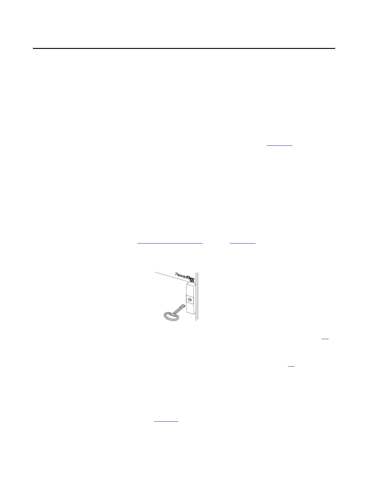
1. Use the double-bit key provided to open the power bay door.
2. Remove the protective touch guards to access components, mechanical
and electrical connections. See Remove Protective Guards on page 70
for instructions for removing the guards that are found in each enclosure
type.
3. Review Component Removal Requirements on page 60
to determine
which power and LCL filter modules you need to remove to facilitate
installation.
4. Remove the power modules and LCL filter modules identified for the
product you are installing.
Each module is marked with its unique position number the cabinet. See
Figure 18
.
The PowerFlex 750-Series module service cart, catalog number 20-750-
MCART1 is recommended for moving power modules and LCL filter
modules.
 Loading...


