PowerFlex 750-Series Products with TotalFORCE Control 29
Rockwell Automation Publication 750-PC100A-EN-P - December 2016
Fiber Optic Connections
Fiber optic cable connections between joined cabinets are required. See the PowerFlex 750-Series Products with TotalFORCE Control Installation Instructions, publication 750-IN100, for detailed instructions on how to route and
connect the cables.
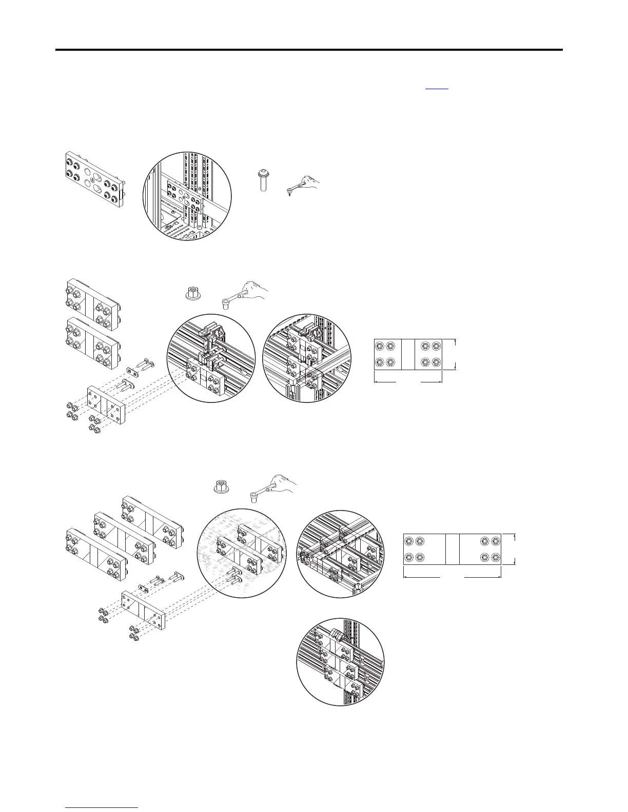
Splice Kits
Splice kits are provided are to make the internal bus bar electrical connections between cabinet shipping sections.s
PE Ground Bar
DC Bus Bars
Top AC Bus Bars, AC Motor Out/Entry Wire Bay Bus Bars
M10
38.0 N•m (336 lb•in)
15 mm
85 mm
(3.3 in.)
186 mm
(7.3 in.)
M10
38.0 N•m (336 lb•in)
15 mm
85 mm
(3.3 in.)
268.5 mm
(10.6 in.)
AC Top Bus Bar Splice
AC Motor Out/Entry Wire Bay Splice
 Loading...


