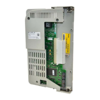
PowerFlex® DC Drive - Frame A Switching Power Supply Circuit Board 15
11. Remove the plastic stand-off and nut that secures the Switching Power
Supply board to the back of the Pulse Transformer board.
Step 5: Install the Existing
Pulse Transformer Board
and New Switching Power
Supply Board
Install the existing Pulse Transformer board and new Switching Power
Supply board in reverse order of removal as detailed in Step 4: Remove the
Existing Pulse Transformer and Switching Power Supply Boards on page 7.
• Replace the 16 pin cable connected to connector XA on the Switching
Power Supply board with the new cable provided (refer to Figure 2 on
page 14 above for location).
Step 6: Install the Control
EMI Shield and Control
Board
Install the Control EMI Shield and Control board in the reverse order of
removal as detailed in Step 3: Remove the Control EMI Shield and Control
Board on page 5.
Secure nut
Remove stand-off

 Loading...


