PowerFlex® DC Drive - Frame A Switching Power Supply Circuit Board 7
Step 4: Remove the
Existing Pulse Transformer
and Switching Power Supply
Boards
Note: The Switching Power Supply circuit board is mounted on the back of
the Pulse Transformer circuit board. You must remove both boards in order
to replace the Switching Power Supply board.
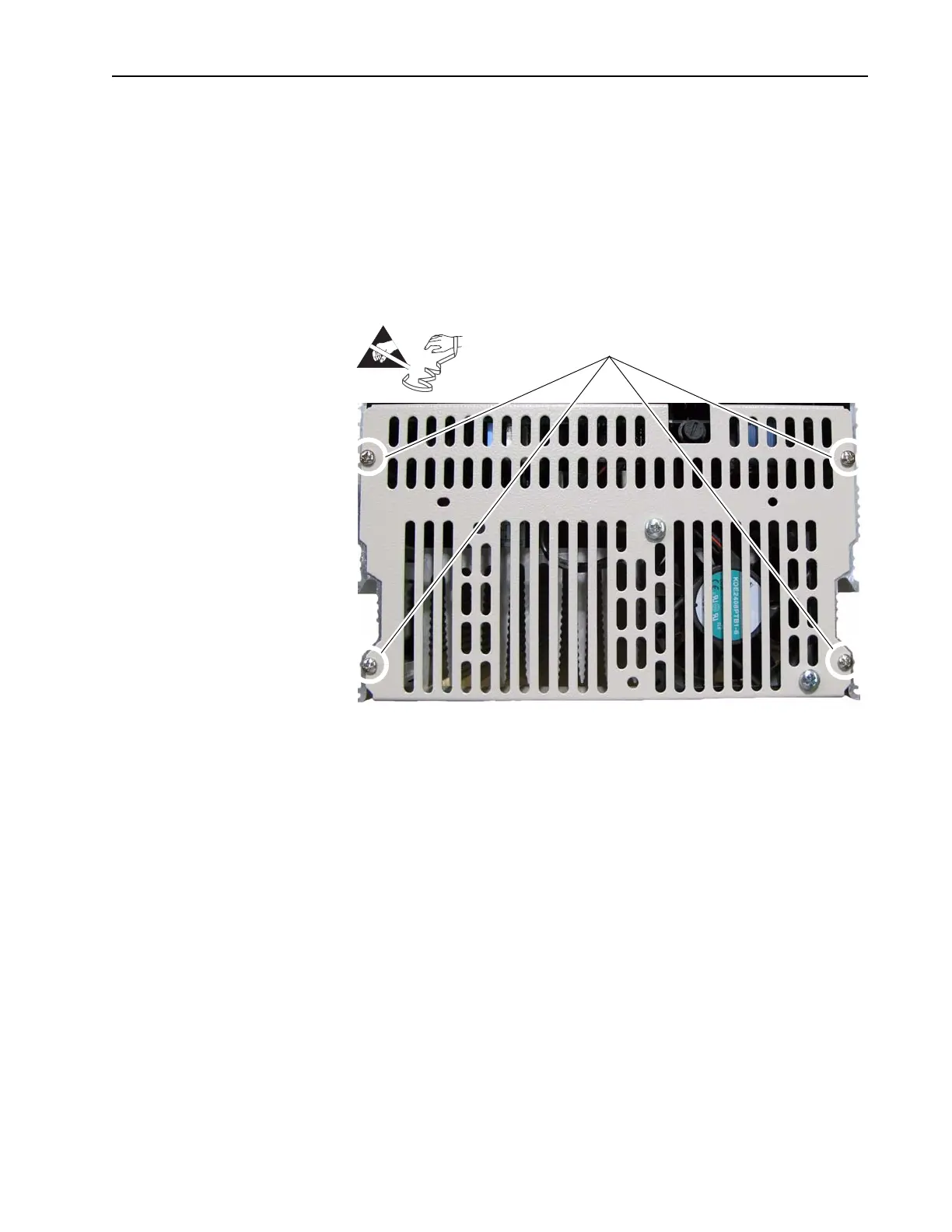
1. Remove the air flow plate from the top of the drive:
– For 38A and 55A drives @ 230V AC input and 35A, 45A, and 52A
drives @ 460V AC input, remove the four screws that secure the
slotted air flow plate to the top of the drive, remove the fan cable from
connector XV on the Switching Power Supply board and remove the
plate and connected fan.
=
Remove screws

 Loading...


