EasyManuals Logo

Allen-Bradley PowerFlex Installation Instructions

Allen-Bradley PowerFlex
16 pages
To Next Page IconTo Next Page
To Previous Page IconTo Previous Page
Page #14 background imageLoading...
Page #14 background image
14 PowerFlex® DC Drive - Frame A Switching Power Supply Circuit Board
Figure 2 Switching Power Supply Circuit Board Layout
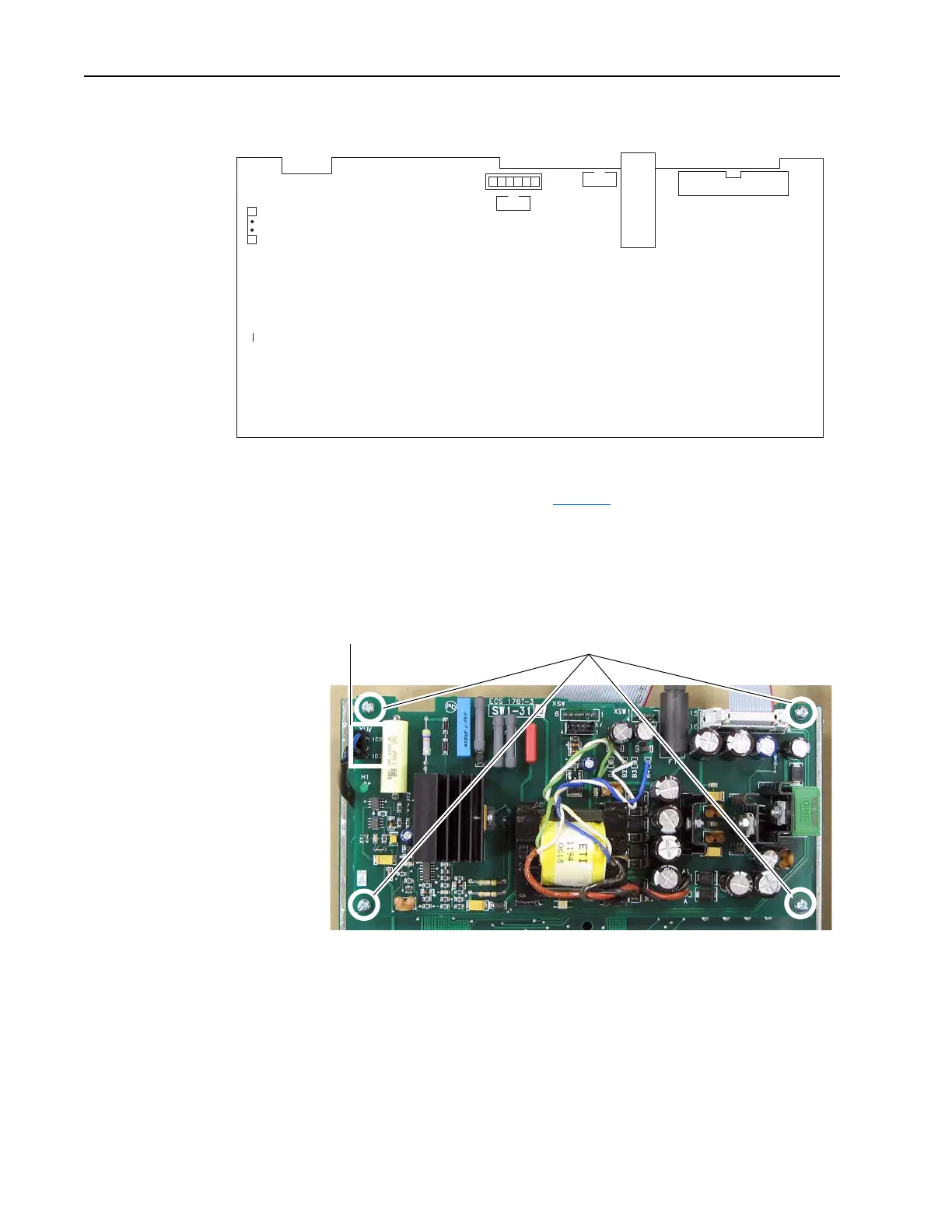
9. Remove the cable from connector XUV on the left side of the Switching
Power Supply board (refer to Figure 2
above for location).
10. Remove the four screws that secure the Switching Power Supply board
to four of the stand-offs on the back of the Pulse Transformer board and
remove the Switching Power Supply board.
XA
1
2
15
16
61
XSW
XY1
14
XSW1
14
XV
F1
1C2
1D2
XUV
Remove screws
Remove cable

Other manuals for Allen-Bradley PowerFlex

Questions and Answers:

Question and Answer IconNeed help?

Do you have a question about the Allen-Bradley PowerFlex and is the answer not in the manual?

Allen-Bradley PowerFlex Specifications

General IconGeneral
CategoryDC Drives
ManufacturerAllen-Bradley
SeriesPowerFlex
Communication OptionsEtherNet/IP, DeviceNet, ControlNet
Protection FeaturesOvercurrent, Overvoltage, Undervoltage, Overtemperature, Short Circuit
Enclosure TypeNEMA 1, NEMA 12, NEMA 4/4X
Operating Temperature0°C to 40°C (32°F to 104°F)
Storage Temperature-40°C to 70°C (-40°F to 158°F)
Humidity5% to 95% (non-condensing)
AltitudeUp to 1000m (3280 ft) without derating

Related product manuals