PowerFlex® DC Drive - Frame A Switching Power Supply Circuit Board 13
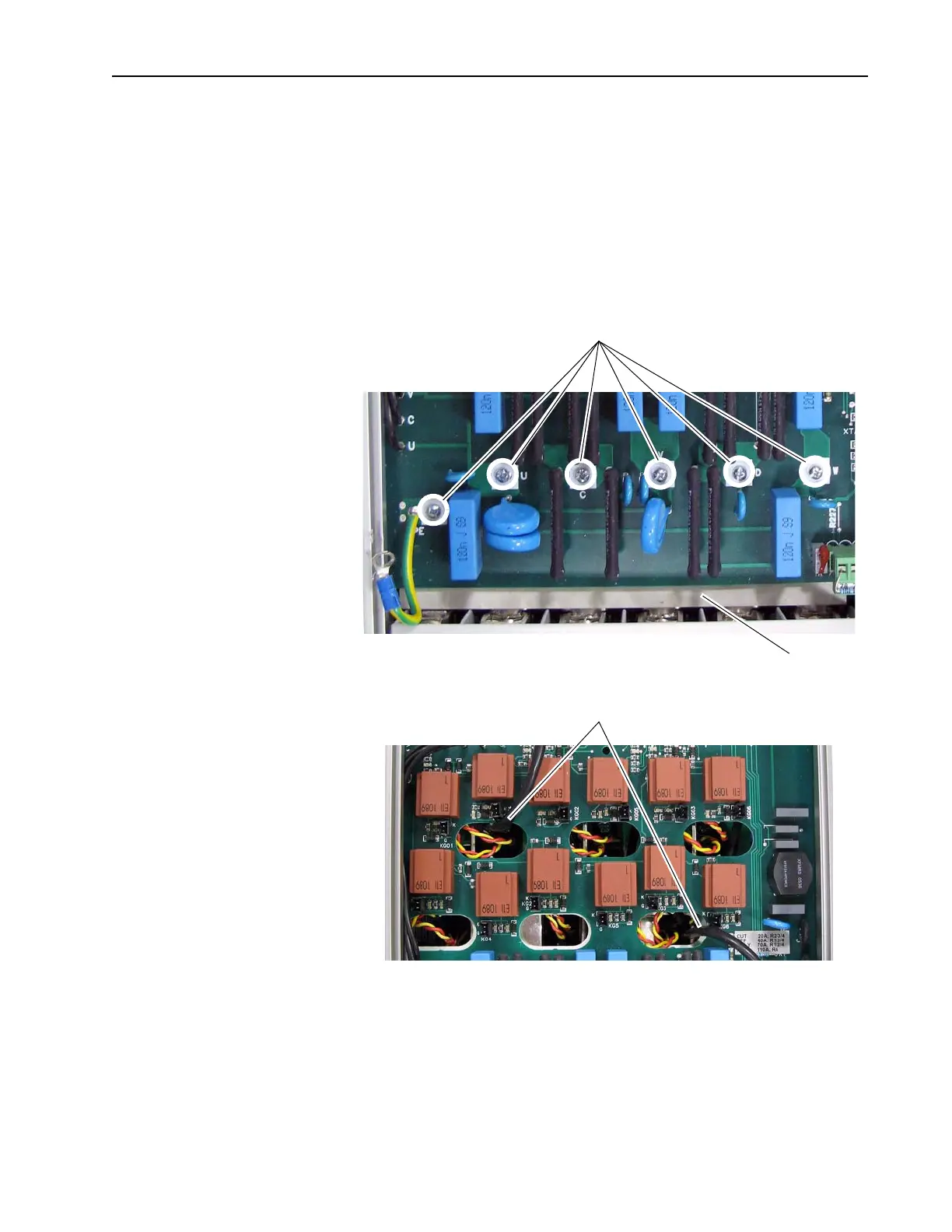
8. Remove the six screws that secure the bottom of the Pulse Transformer
board to the drive and, while lifting up slightly on the board, slide it
toward the top of the drive and out of the chassis. Note that on some
drives there is an isolation sheet below the board; do not remove this
sheet.
Important: The cables from connectors XSW and XTA must slide
through the openings in the board as it is lifted out of the
drive chassis. Take care not to damage these cables and
connectors.
Remove six screws
Carefully route cables through
openings as the board is removed.
Isolation sheet
Note: Regenerative drive shown
 Loading...


