SLC 5/03, SLC 5/04, and SLC 5/05 Modular Processors 7
Publication 1747-IN009E-MU-P - April 2007
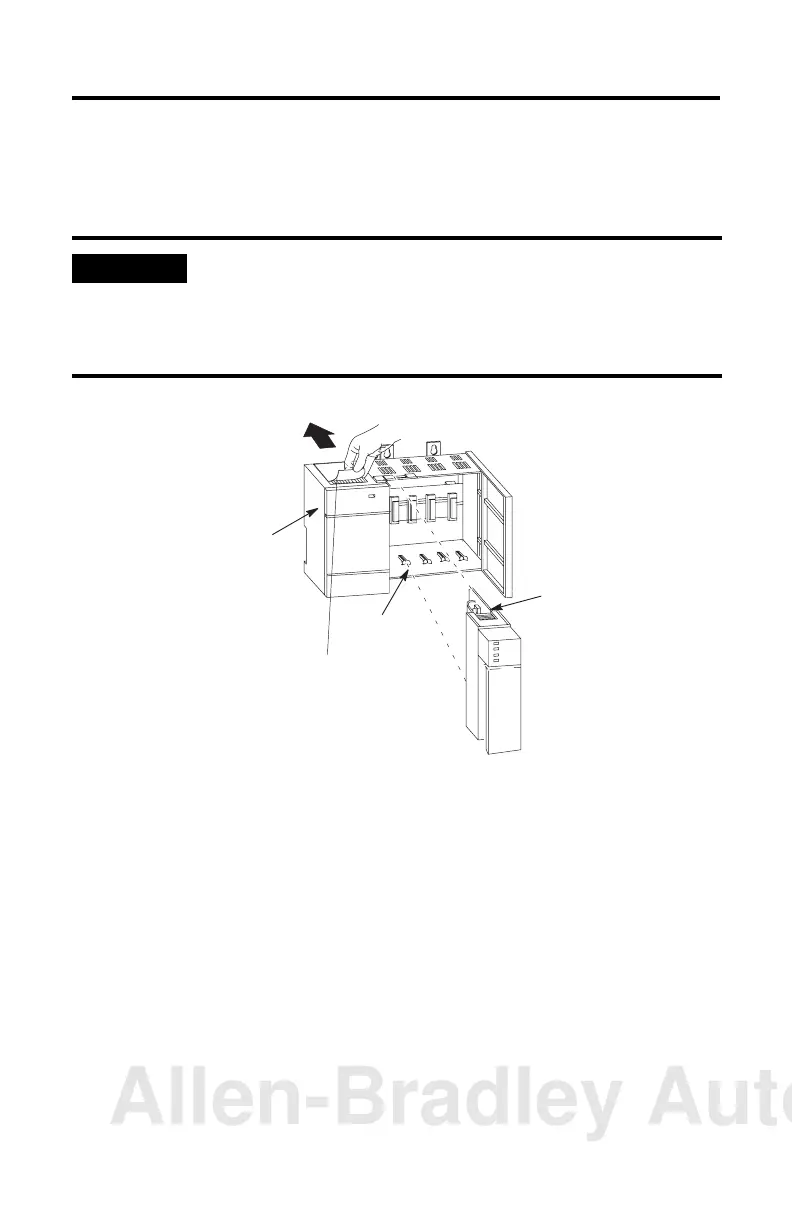
Install the SLC Processor
Make sure system power is off; then insert the processor into slot 0 of the 1746
chassis.
Apply Power to the Processor
1. Energize the chassis power supply.
2. Check the chassis power supply and processor LED indicators. The power
LED indicator on the power supply should be on and the fault LED indicator
on the processor should be flashing.
See the figure on page 8 for location of the power supply and processor LED
indicators.
IMPORTANT
The SLC 500 modular processors must be inserted into the left slot (slot 0).
Inserting the processor in another slot won’t allow the processor to operate.
In addition, remove the protective wrap after installing the processor. Failure to
remove the wrap can cause the power supply to overheat.
Power
Supply
Protective Wrap
Card Guide
Processor Release
Allen-Bradley Automation
 Loading...