AT-8000 Series Fast Ethernet Switches Installation Guide
85
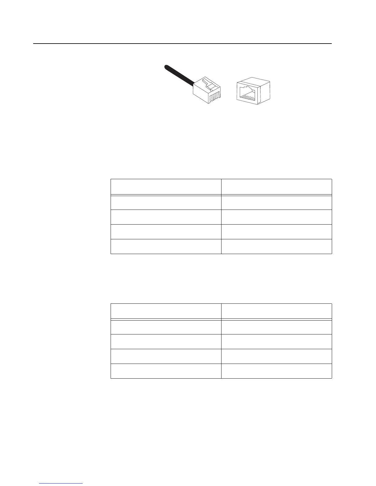
RJ-45 Twisted Pair Port Pinouts
Figure 40 illustrates the pin layout to an RJ-45 connector and port.
Figure 40. RJ-45 Connector and Port Pin Layout
Table 9 lists the RJ-45 pin signals when a twisted pair port is operating in
the MDI configuration at 10 or 100 Mbps.
Table 10 lists the RJ-45 port pin signals when a twisted pair port is
operating in the MDI-X configuration at 10 or 100 Mbps.
Table 9. MDI Pin Signals (10/100Base-TX)
Pin Signal
1TX+
2TX-
3RX+
6RX-
Table 10. MDI-X Pin Signals (10/100Base-TX)
Pin Signal
1RX+
2RX-
3TX+
6TX-
8
8
1
1
 Loading...