10Base-T (UTP) Connections
Micro Repeaters with a UTP port support both straight-through (Figure 2) and
crossed (Figure 3) wiring. The MDI/MDI-X two-position slide switch located
near the RJ45 connector will allow use with either type of cable. If you are not
sure of the UTP cable pinout, set the switch into the position that gives a valid
Link indication for the UTP connection.
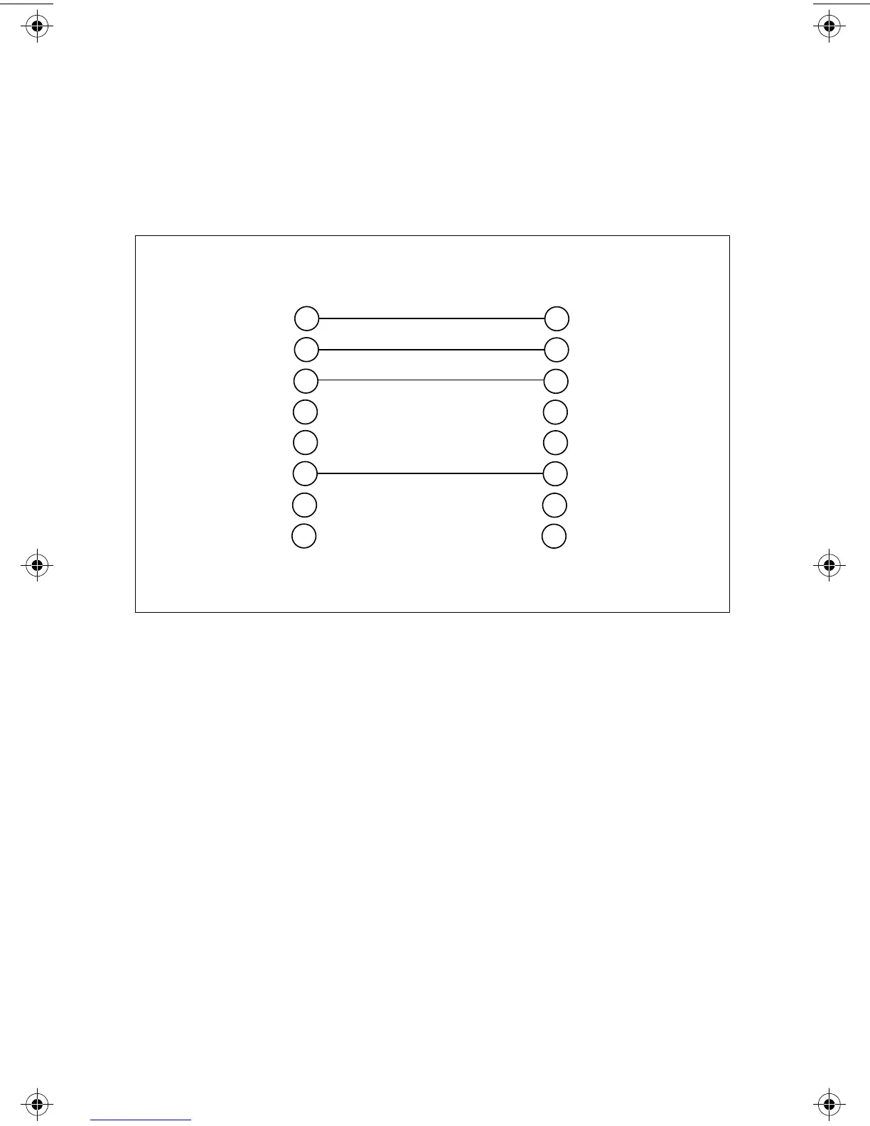
Figure 2:
10Base-T UTP Straight-Through
1
2
3
4
5
6
7
8
1
2
3
4
5
6
7
8
TD +
TD -
RD +
Not Used
TD +
TD -
RD +
Not Used
Not Used
Not Used
Not Used
Not Used
Not Used
Not Used
RD -
RD -
RJ45 PIN
RJ45 PIN
Per IEEE 802.3 specifications
3
MR11x/MR12x.4Web Page 11 Monday, February 24, 1997 11:33 AM
 Loading...