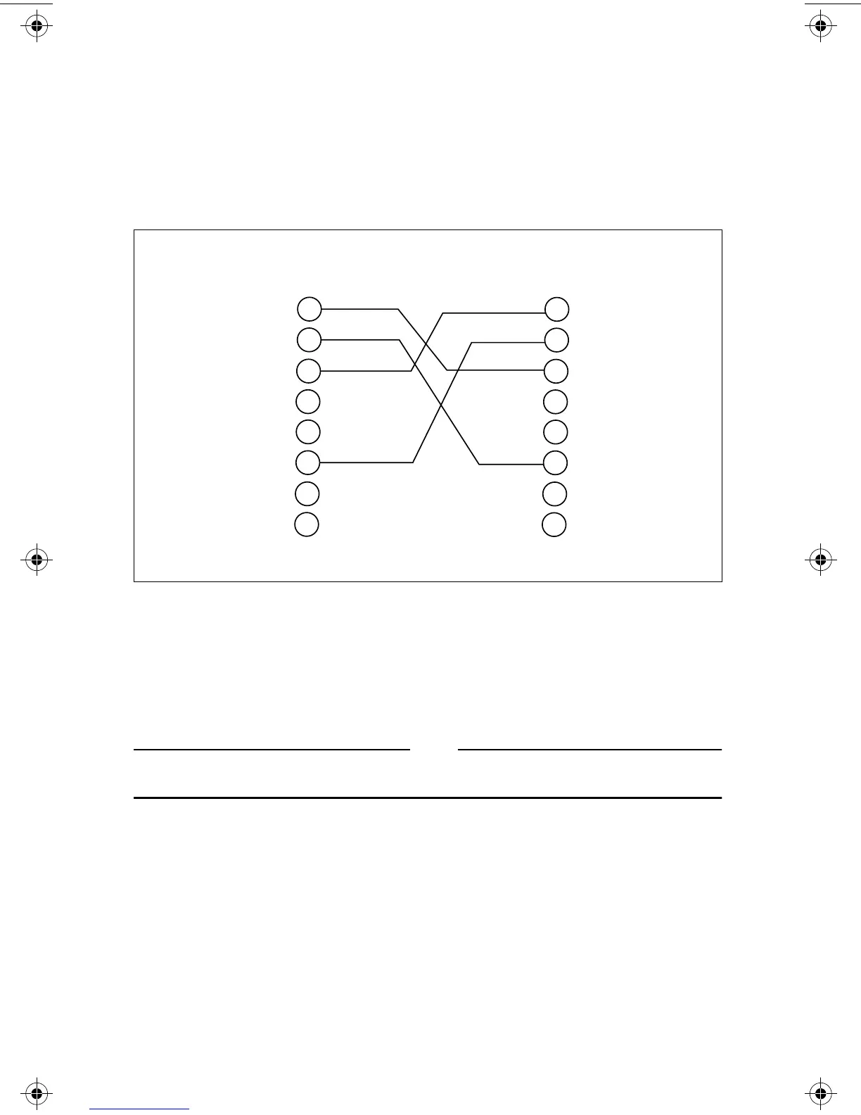
This switch allows for use with a UTP cable wired as straight-through (MDI
interface) or wired with the TX pair crossed with the RX pair (MDI-X interface).
That is, when connecting the micro repeater to a 10Base-T repeater or Hub, a
straight-through cable could be used and the switch would be in the
non-crossover position (MDI). If the UTP port is connected to a 10Base-T
transceiver and a straight-through cable is used, then the switch should be in
the crossover (MDI-X) position.
Figure 3:
10Base-T UTP Crossover Cabling
External Power Supply Micro Repeaters
The AT-MR11x Micro Repeaters have external power adapters. Locate a 120
VAC outlet and plug in the provided AC power adapter.
Note
Use only the AC power adapter provided. Using another power adapter may
permanently damage your micro repeater and void your warranty.
Connect the power connector from the AC power adapter to the micro repeater.
The power indicator should illuminate.
1
2
3
4
5
6
7
8
1
2
3
4
5
6
7
8
TD +
TD -
RD +
Not Used
TD +
TD -
RD +
Not Used
Not Used
Not Used
Not Used
Not Used
Not Used
Not Used
RD -
RD -
RJ45 PIN
RJ45 PIN
Per IEEE 802.3 specifications
4
MR11x/MR12x.4Web Page 12 Monday, February 24, 1997 11:33 AM
 Loading...