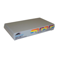
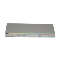
Internal Power Supply Micro Repeaters
The AT-MR12x Micro Repeaters have internal universal power supplies.
Locate the 120 or 240 VAC power outlet for the site and plug in the standard-
equipment power cord. Insert the power plug into the micro repeater. The
power indicator should now illuminate.
The CentreCOM Micro Repeaters re-time the Ethernet signal and regenerate
the Ethernet packet and preamble. The micro repeaters also count the number
of consecutive collisions. If this number reaches 32, then the repeater takes the
segment Off Line (partition). If one valid Ethernet packet is received on that
segment, the repeater places the segment On Line automatically, thus,
disconnecting problem segments and reconnecting valid segments dynamically.
Switches
Micro repeaters with an UTP RJ45 port (the AT-MR111T, AT-MR121T,
AT-MR112T and AT-MR122T) have a switch for selecting the UTP crossover
function. Models with a BNC port (the AT-MR112T, AT-MR122T, AT-MR114T,
AT-MR124T, AT-MR115 and AT-MR125) have a switch for selecting or
deselecting the internal 50
Ω
termination function for the thinnet connection.
Note
The factory default of the 50
Ω
terminator switch is the ON setting. No external
BNC-T and 50
Ω
terminator is required when this switch is enabled.
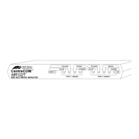
Indicators
The following diagnostic indicators are common to the micro repeaters:
Power—
Indicates the AC power adapter is plugged in and providing power to
the micro repeater.
On Line—
This indicator is lit when the port is ready for operation and is not
partitioned.
Collision—Indicates a collision detected on that port.
Receive—This indicator will flash whenever a packet is received on that port.
Brief flashes indicate low traffic levels.
Transmit—Indicates micro repeater transmitting a packet out of that port. In
addition to the common indicators, the 10Base-T RJ45 ports have a Link
indicator.
Link—This indicator will illuminate when a valid link is detected on the
Receive pair of the UTP segment. The Link indicator must be lit on the
10Base-T devices on both ends of the UTP segment for Ethernet data to flow.
5
MR11x/MR12x.4Web Page 13 Monday, February 24, 1997 11:33 AM
 Loading...