1. Verify that the segment is properly terminated on both ends and that there
is no other termination between these two points. You may plug the BNC
connector directly into the micro repeater BNC connection if the internal
50 Ω termination function is enabled. If a BNC-T connector is to be used, the
internal 50 Ω termination function should be disabled. Using an Ohm meter
(DMM or VOM), it is possible to statically test the coaxial segment. With
terminators in place, measure the resistance of the cable from the male
connector of a BNC-T. Touch one of the meter's probes to the inner pin and
the other probe to the outside of the BNC-T. You should read between 25 Ω
and 30 Ω resistance.
Caution
Too many collisions.
1. On an AUI port, make certain that the SQE Test (heartbeat) switch is OFF
on any transceiver attached to the port.
2. Check the media connections and cabling. Excessive collisions may be caused
by a faulty cable or connection.
Network loading can also cause excessive collisions.
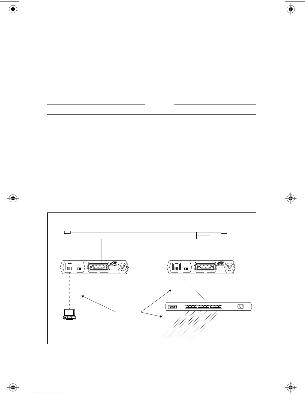
Configurations
The configuration in Figure 14 demonstrates how the AT-MR111T (or
AT-MR121T) can be used to connect 10Base-T devices.
Figure 14: AT-MR111T AUI to RJ45
MR111T
IEEE 802.3
MICRO REPEATER
CentreCOM
POWER
AUI
PORT 1PORT 2
MDI MDI X
10BASE T
TM
MR111T
IEEE 802.3
MICRO REPEATER
CentreCOM
POWER
AUI
PORT 1PORT 2
MDI MDI X
10BASE T
TM
10BASE5
XCVR
10BASE5
XCVR
10Base5 Thick Ethernet
500 Meters and 100 MAUs Max.
10Base-T UTP
100 Meters Max.
2 MAU Max. (Pt. to Pt.)
50 Ω
Terminator
50 Ω
Terminator
POWER
1211109 8765 4321
XXXX XXXX XXXX
10BASET NET WORK PORTS 1-12
AUI PORT
11
MR11x/MR12x.4Web Page 19 Monday, February 24, 1997 11:33 AM
 Loading...