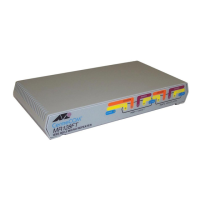
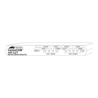
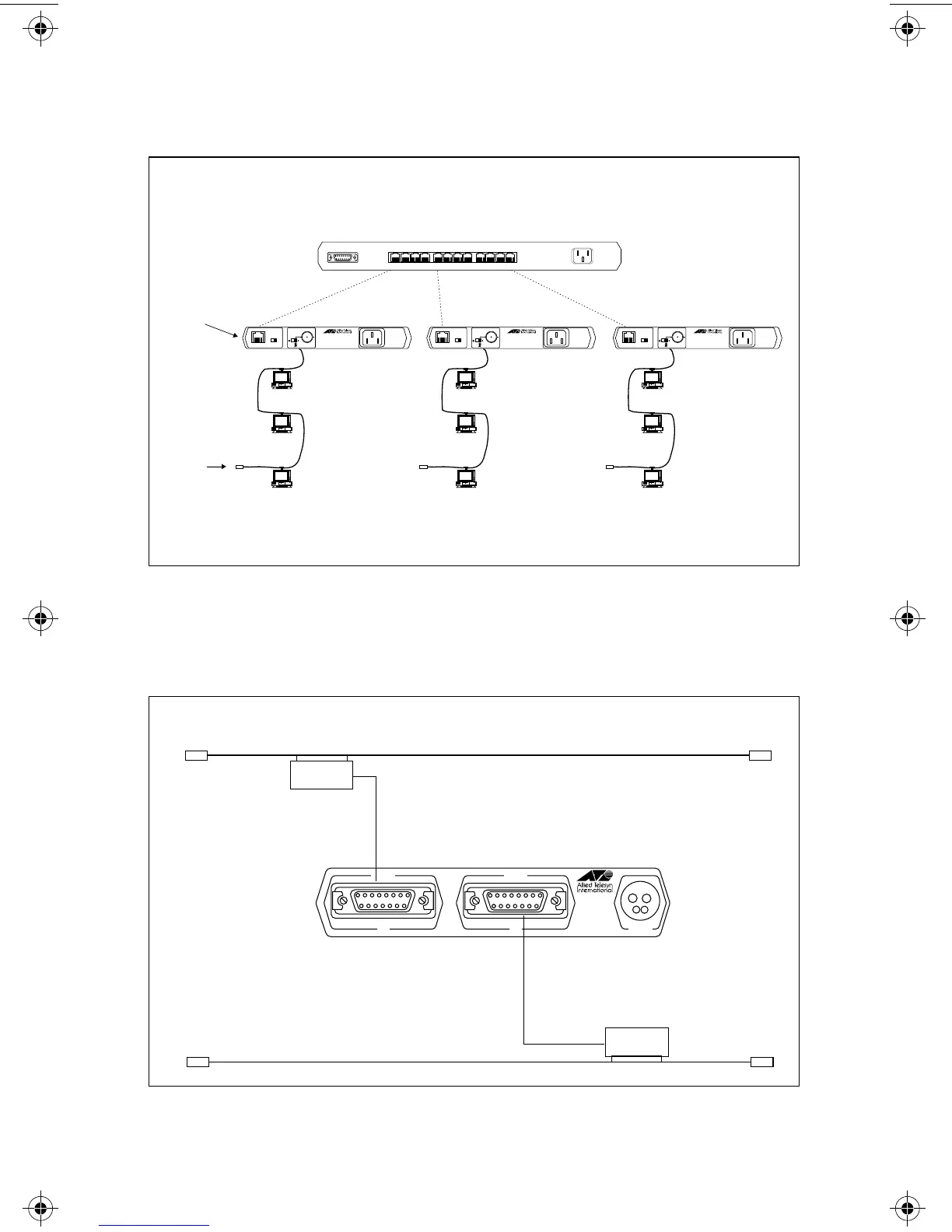
The configuration in Figure 15 depicts a 10Base-T Hub connecting to several
10Base2 segments through the AT-MR122T (or AT-MR112T) micro repeater.
Figure 15: AT-MR122T BNC to RJ45
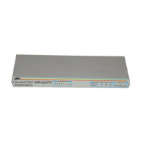
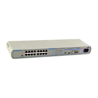
The configuration in Figure 16 shows how an AT-MR113 (or AT-MR123)
connects two 10Base5 segments.
Figure 16: AT-MR113 AUI to AUI
10Base-T UTP
100 Meters Max.
2 MAU Max. (Pt. to Pt.)
10BASE-T
PORT 2
POWER
10BASE 2
PORT 1
CentreCOM
TM
MR122T
IEEE 802.3 MICRO REPEATER
OFF ON
TERMINATOR
RJ45 PIN-OUT
MDI MDI X
10BASE-T
PORT 2
POWER
10BASE 2
PORT 1
CentreCOM
TM
MR122T
IEEE 802.3 MICRO REPEATER
OFF ON
TERMINATOR
RJ45 PIN-OUT
MDI MDI X
10BASE-T
PORT 2
POWER
10BASE 2
PORT 1
CentreCOM
TM
MR122T
IEEE 802.3 MICRO REPEATER
OFF ON
TERMINATOR
RJ45 PIN-OUT
MDI MDI X
Thin Ethernet
185 Meters Max.
30 MAU Max.
50 Ω
Terminator
Media Converter
(Repeater)
POWER
1211109 8765 4321
XXXX XXXX XXXX
10BASE T NETWORK PORTS 1-12
AUI PORT
MR
113
IEEE 802.3
MICRO REPEATER
CentreCOM
POWER
AUI
PORT 1
AUI
PORT 2
TM
AT-206
AT-206
10Base5 Thick Ethernet
10Base5 Thick Ethernet
12
MR11x/MR12x.4Web Page 20 Monday, February 24, 1997 11:33 AM
 Loading...