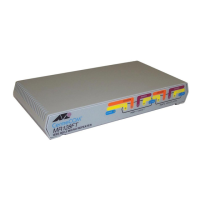
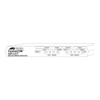
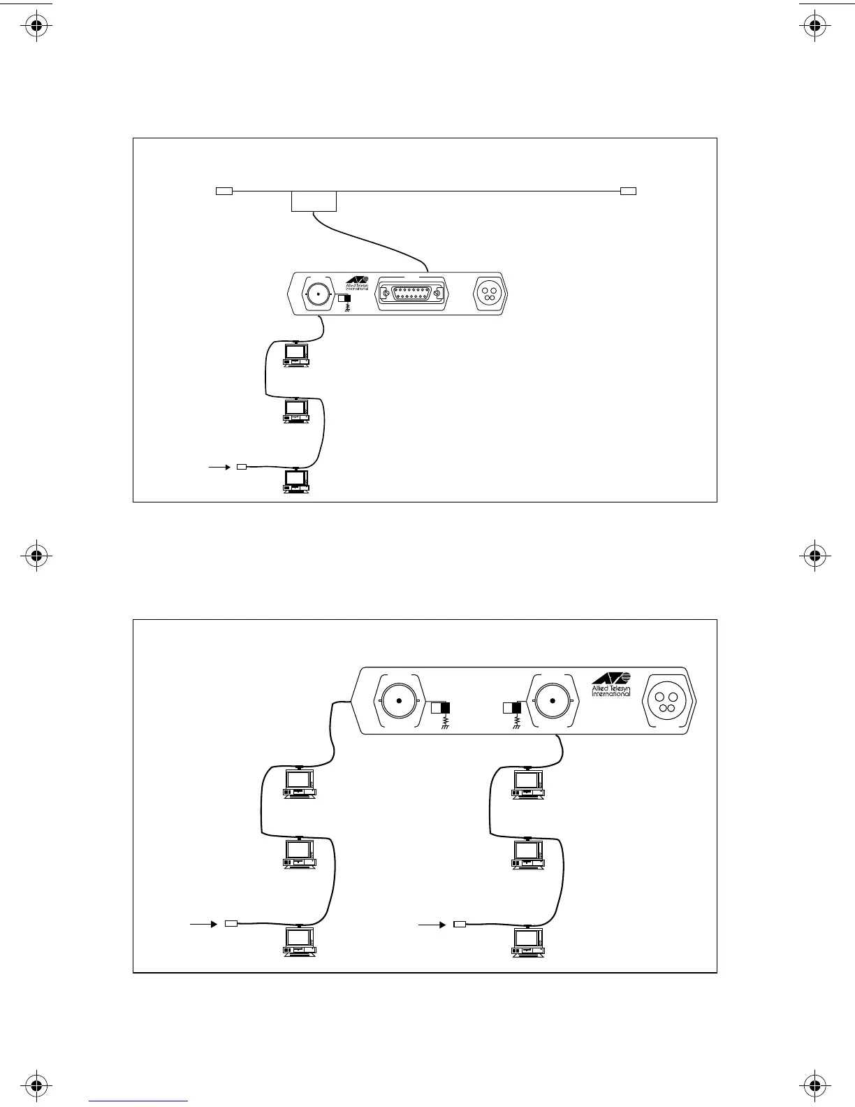
Figure 17 shows how an AT-MR114 (or AT-MR124) connects a 10Base2
segment to a 10Base5 backbone.
Figure 17: AT-MR114 AUI to BNC
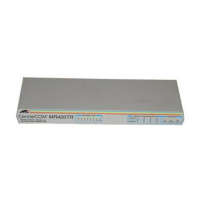
The configuration in Figure 18 shows how an AT-MR115 (or AT-MR125) would
be used to connect two 10Base5 segments.
Figure 18: AT-MR115 BNC to BNC
10Base5
XCVR
10Base5 Thick Ethernet
500 Meters and 100 MAU Max.
AUI Cable 50 Meters Max.
50 Ω
Terminator
50 Ω
Terminator
50 Ω
Terminator
Thin Ethernet
185 Meters Max.
30 MAU Max.
10 BASE2
POWER
AUI
TERMINATOR
MR114
IEEE 802.3
MICRO REPEATER
CentreCOM
PORT 2 PORT 1
O
F
F
O
N
TM
50 Ω
Terminator
Thin Ethernet
185 Meters Max.
30 MAU Max.
50 Ω
Terminator
Thin Ethernet
185 Meters Max.
30 MAU Max.
MR115
IEEE 802.3
MICRO REPEATER
CentreCOM
O
F
F
O
N
POWER
10BASE2
PORT 1
10BASE2
PORT 2
O
F
F
O
N
TERMINATOR TERMINATOR
TM
13
MR11x/MR12x.4Web Page 21 Monday, February 24, 1997 11:33 AM
 Loading...