EasyManuals Logo

Allied Telesis x510 Series User Manual

Allied Telesis x510 Series
20 pages
To Next Page IconTo Next Page
To Previous Page IconTo Previous Page
Page #11 background imageLoading...
Page #11 background image
11
Preface
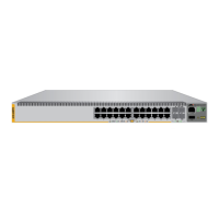
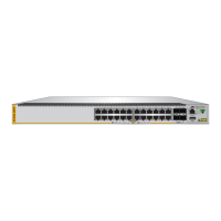
This guide contains the installation instructions for the x510 Series of
Layer 2+ and Basic Layer 3, Gigabit Ethernet switches. This preface
contains the following sections:
“Document Conventions” on page 12
“Contacting Allied Telesis” on page 13
Note
This guide explains how to install the switches as stand-alone units.
For instructions on how to install them in a stack configuration with
Virtual Chassis Stacking (VCStack
), refer to the x510 Series
Installation Guide for Virtual Chassis Stacking.

Other manuals for Allied Telesis x510 Series

Questions and Answers:

Question and Answer IconNeed help?

Do you have a question about the Allied Telesis x510 Series and is the answer not in the manual?

Allied Telesis x510 Series Specifications

General IconGeneral
Seriesx510 Series
CategorySwitch
Operating Temperature0°C to 50°C (32°F to 122°F)
MAC Address Table Size16K entries
VLANs4094
Jumbo Frames9KB
Power SupplyInternal power supply, 100-240V AC, 50/60Hz
StackingUp to 8 units
LayerLayer 2
Power over Ethernet (PoE)Available on some models
ManagementWeb-based, CLI, SNMP
Security FeaturesAccess Control Lists (ACLs), 802.1X authentication, port security
WeightVaries by model
PortsVaries by model (e.g., 24, 48)
Dimensions (W x D x H)440 x 260 x 44 mm (x510-52GP), 440 x 260 x 44 mm (x510-28GP)

Related product manuals