507276-03Page 18 of 59 Issue 1621
Exhaust Piping (Figures 25 and 26)
1. In areas where piping penetrates joist or interior walls,
hole must be large enough to allow clearance on all
sides of pipe through center of hole using a hanger.
2. When furnace is installed in a residence where unit is
shut down for an extended period of time, such as a
vacation home, make provisions for draining condensate
collection from trap and lines.
3. Route piping to outside of structure. Continue with
installation following instructions given in piping
termination section.
Vent Piping Guidelines
This gas furnace can be installed as either a Non-Direct
Vent or a Direct Vent gas central furnace.
NOTE: In non-Direct Vent installations, combustion air is
taken from indoors and ue gases are discharged outdoors.
In Direct Vent installations, combustion air is taken from
outdoors and ue gases are discharged outdoors.
Intake and exhaust pipe sizing - Size pipe according to
Tables 4, 5 and 6. Table 4 lists the minimum vent pipe
lengths permitted. Table 5 and 6 list the maximum pipe
lengths permitted.
Regardless of the diameter of pipe used, the standard roof
and wall terminations described in section Exhaust Piping
Terminations should be used. Exhaust vent termination
pipe is sized to optimize the velocity of the exhaust gas as
it exits the termination. Refer to Table 8.
Figure 22
CHIMNEY
OR GAS
VENT
(Check sizing
for remaining
appliance)
FURNACE
(Removed from
from common
vent system)
WATER
HEATER
OPENINGS
(To Adjacent
Room)
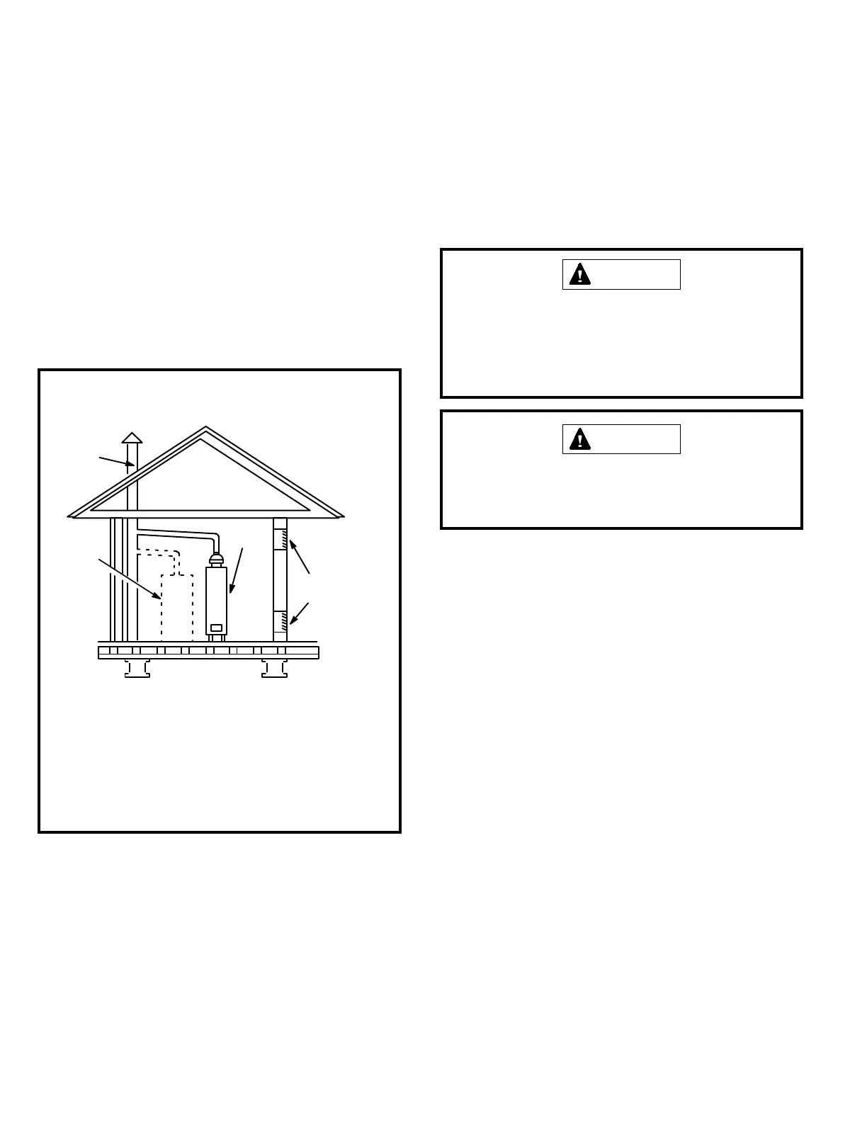
If this gas furnace replaces a furnace which
was commonly vented with another gas appliance,
the size of the existing vent pipe for that gas
appliance must be checked. Without the heat of the
original furnace flue products, the existing vent pipe
is probably oversized for the single water heater or
other appliance. The vent should be checked for
proper draw with the remaining appliance.
REPLACING FURNACE THAT
WAS PART OF A COMMON
VENT SYSTEM
5. After the main burner has operated for 5 minutes, test
for leaks of ue gases at the draft hood relief opening.
Use the ame of a match or candle.
6. After determining that each appliance connected to
the common venting system is venting properly, (step
3) return all doors, windows, exhaust fans, replace
dampers, and any other gas burning appliances to their
previous mode of operation.
7. If a venting problem is found during any of the preceding
tests, the common venting system must be modied to
correct the problems.
Resize the common venting system to the minimum vent
pipe size determined by using the appropriate tables in
Appendix G. (These are in the current standards of the
National Fuel Gas Code ANSI Z223.1.
Do not discharge exhaust into an existing stack or
stack that also serves another gas appliance. If vertical
discharge through an existing unused stack is required,
insert PVC pipe inside the stack until the end is even
with the top or outlet end of the metal stack.
CAUTION
The exhaust vent pipe operates under positive pressure
and must be completely sealed to prevent leakage of
combustion products into the living space.
CAUTION