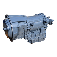
Do you have a question about the Allison Transmission 3200 SP and is the answer not in the manual?
Explains the three types of headings used to attract attention in the manual.
Describes how to select forward and reverse ranges for transmission operation.
Introduces the FuelSense® 2.0 packages for fuel economy.
Defines key terms and features associated with FuelSense® 2.0.
Explains the purpose, operation, and benefits of the hydraulic retarder.
Outlines the importance and procedures for performing regular inspections.
Lists the approved fluids and specifications for Allison transmissions.
Outlines methods for checking transmission fluid levels.
Describes how to check transmission fluid level using a dipstick.
Details the procedure for checking fluid level when the transmission is cold.
Details the procedure for checking fluid level when the transmission is at operating temperature.
Explains how to check fluid levels electronically using shift selectors.
Provides the step-by-step procedure for electronic fluid level checks.
Lists the requirements for using Prognostics features and functions.
Details the steps to enable or disable the Prognostics feature.
Explains how to set the transmission fluid type for accurate prognostics.
Describes the OM feature which monitors fluid life and alerts for changes.
Explains the notification system for required fluid changes based on OM.
Details how to read and reset the OM using the shift selector.
Describes the FM feature that alerts when transmission filters need replacement.
Explains the notification system for required filter changes based on FM.
Provides an overview of diagnostic features and Diagnostic Trouble Codes (DTCs).
Explains how the control system responds to active Diagnostic Trouble Codes (DTCs).
Describes the function and meaning of the CHECK TRANS indicator light.
Explains how to access diagnostic information using the shift selector.
Describes the sequence in which DTCs are displayed on the shift selector.
Details how to read and clear DTCs using a keypad push button selector.
Details how to read and clear DTCs using a bump-shift lever selector.
Steps for reading DTCs with Prognostics on using a bump-shift lever.
Steps for reading DTCs with Prognostics off using a bump-shift lever.
Procedure for clearing DTCs using a bump-shift lever selector.
Describes various display conditions related to DTCs and inhibits.
| Enclosure Rating | IP67 |
|---|---|
| Input Voltage | 12/24 VDC |
| Operating Temperature Range | -40°C to +85°C |
| Communication Protocol | SAE J1939 |
| Memory | Flash and EEPROM |
| Diagnostic Capabilities | fault code logging |
| Dimensions | Varies by model |
| Weight | Varies by model |
| I/O | Digital and Analog Inputs/Outputs |
| Type | Transmission Electronic Control Unit (TECU) |


